Distributed multi-channel coherent optical fiber sensing system

a multi-channel coherent, optical fiber technology, applied in the direction of optical apparatus testing, reflectometers detecting back-scattered light in frequency-domain, instruments, etc., can solve the problems of time-consuming, expensive, and even impossible to implement an extra special communication cable, and achieve the effect of reducing the cost of implementation, time-consuming and expensiv

Active Publication Date: 2016-07-14
NEC CORP
View PDF0 Cites 20 Cited by
  • Summary
  • Abstract
  • Description
  • Claims
  • Application Information

AI Technical Summary

Problems solved by technology

Nonetheless, the optical couplers (optical isolators and optic terminators) in both cases reduce the optical power of forward signal or back reflection, wasting the precious carried information along with it.
This may create big challenges in the establishment of a long-term, high-speed, and stable communication method between sensing edges and receiver terminals.
The implementation of an extra special communication cable will be time consuming, costly, and even technically impossible, for some cases.
Moreover, this could add additional maintenance costs for the entire sensing system.
So far, there is no mature research that can achieve such duo-functionality, such as signal transmission and distributed sensing, simultaneously within the same fiber.
Another main challenge related to optical fiber sensor systems is how to measure and separate a large number of different measurands, which is a challenge that requires the use of many electronic point sensors.
SMFs, the Brillouin frequency shift, and the Brillouin power change were measured to achieve concurrent temperature and strain sensing, but the spatial resolution was too poor.

Method used


Image

  • Distributed multi-channel coherent optical fiber sensing system
  • Distributed multi-channel coherent optical fiber sensing system
  • Distributed multi-channel coherent optical fiber sensing system

Examples


Embodiment Construction

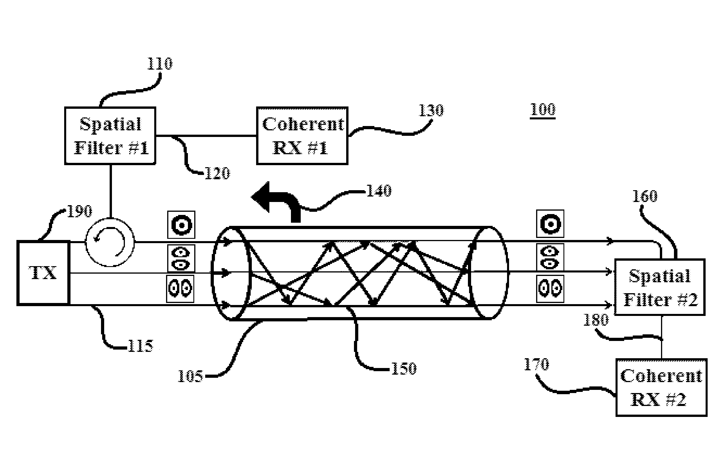
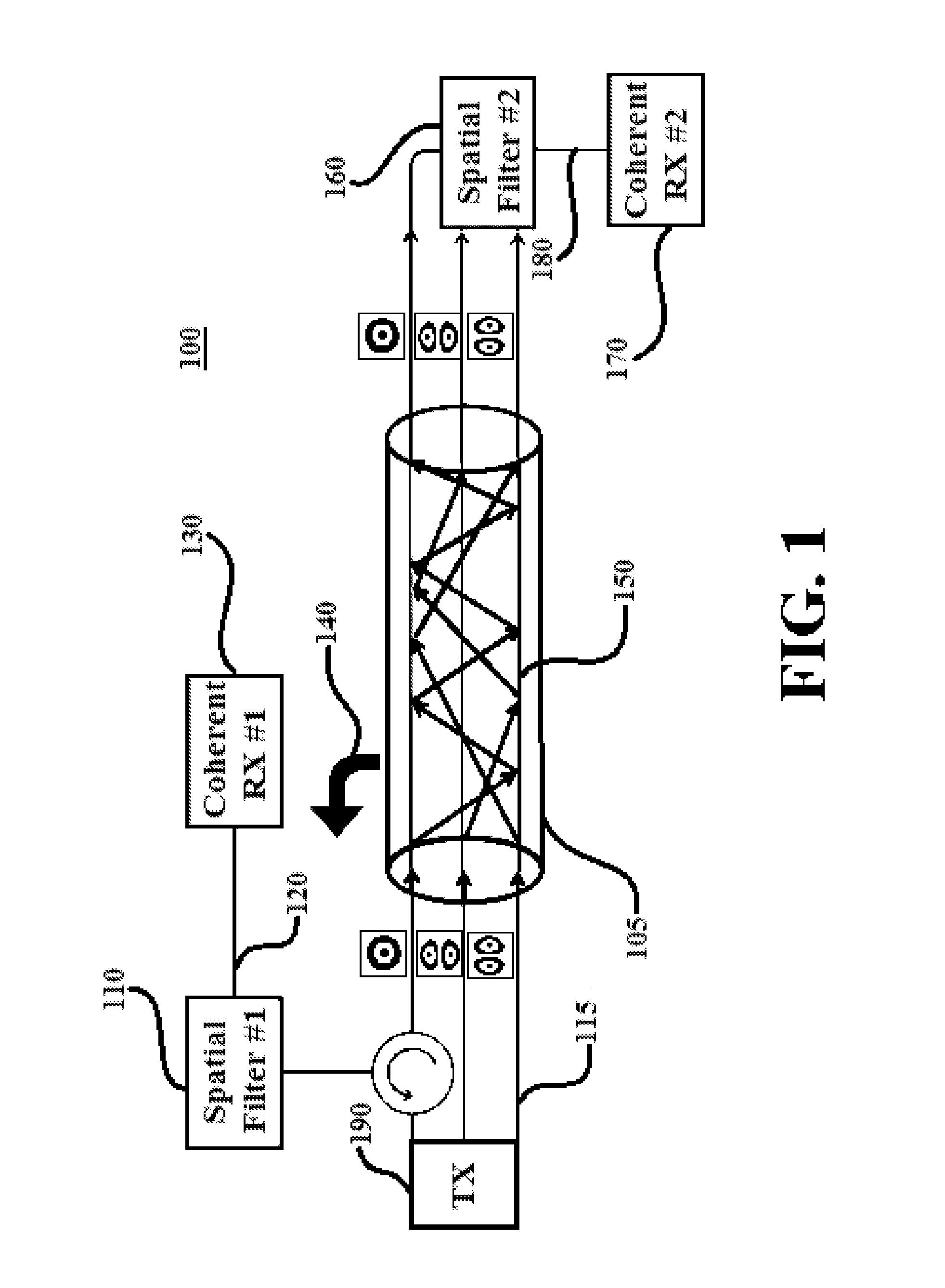
[0017]In accordance with an embodiment of the present principles, systems and methods are provided for simultaneously achieving telecommunications and distributed sensing, using Few-Mode Fibers (FMFs) or Multi-Mode Fibers (MMFs), special filters, coherent detection, and Multiple-Input and Multiple-Output Digital Signal Processing (MIMO-DSP), by employing a distributed multi-channel coherent optical fiber sensing system. By using a correlation between modes, the system is able to take full advantage of both forward signals and backward signals. This provides cost savings for maintenance and the placement of an extra special communication cable, which is a cable that is configured to allow simultaneous signal transmission and distributed sensing.

[0018]No attempt has been made to realize duo-functionality in optical fiber sensor systems because Single-Mode Fibers (SMFs) are not suitable to simultaneously achieve sensing and transmission. In a conventional single-mode fiber (SMF), a fib...


PUM


Abstract

A method and system are provided. The method includes converting, using a spatial mode converter, an input signal into a plurality of spatial modes and performing polarization multiplexing and mode multiplexing, using a polarization multiplexer and a mode multiplexer, respectively, on the input signal. The method further includes injecting the input signal into a fiber optic medium. The method additionally includes applying, using at least one spatial filter in each of a forward and a backward direction within the fiber optic medium, the plurality of spatial modes within the fiber optic medium to transmit the input signal and perform distributed fault sensing on the input signal simultaneously

Description

BACKGROUND[0001]1. Technical Field[0002]The present invention relates to optical fiber systems and, in particular, to a duo-functionality optical fiber sensor system.[0003]2. Description of the Related Art[0004]Optical fiber technology is ideal for telecommunication systems for its low-loss, high-bandwidth, low-dispersion advantages, as well as its immunity to Electromagnetic Interference (EMI). Optical components, such as optical isolators and optical diodes, are usually applied in fiber-optic communication systems and allow the transmission of light in only the forward direction. This is done to prevent unwanted feedback into the optical oscillator. Additionally, an optical fiber sensor system is another significant application of optical fiber technology thanks to its low-cost, its superior sensitivity, its light-weight technology, its electrical-safety, its remote-access, and its ease of being able to be multiplexed.[0005]So far, numerous distributed sensors using Single-Mode Fi...

Claims


Application Information

Patent Timeline
Patent Type & Authority Applications(United States)
IPC IPC(8): G01M11/00G02B6/14
CPCG01M11/3181G01M11/3109G01M11/3172G02B6/14
Inventor WANG, TINGWENG, YI
Owner NEC CORP
Why Eureka
Try Eureka