Method of manufacturing cable and method of manufacturing composite electric wire

a manufacturing method and technology of composite electric wire, which are applied in the direction of insulating conductors/cables, cables, insulated conductors, etc., can solve the problems of low handling of cables and other problems, and achieve excellent composite electric wire, enhanced handling of each cable, and good workability of electric connection of exposure target regions

Inactive Publication Date: 2016-07-14
YAZAKI CORP
View PDF0 Cites 4 Cited by
  • Summary
  • Abstract
  • Description
  • Claims
  • Application Information

AI Technical Summary

Benefits of technology

[0022]According to the method of manufacturing a composite electric wire in the present invention, handleability of each cable is enhanced and thus, workability of electric connection of the exposure target region is good and an excellent composite elect

Problems solved by technology

Therefore, handleability of the cable is low and waste related

Method used


Image

  • Method of manufacturing cable and method of manufacturing composite electric wire
  • Method of manufacturing cable and method of manufacturing composite electric wire
  • Method of manufacturing cable and method of manufacturing composite electric wire

Examples


example 1

According to the Third Mode of the Method of Manufacturing a Cable

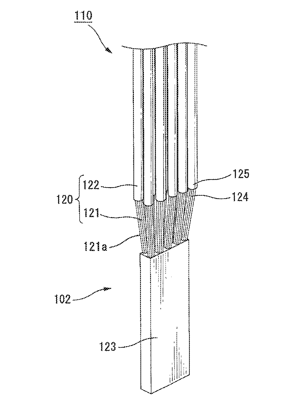
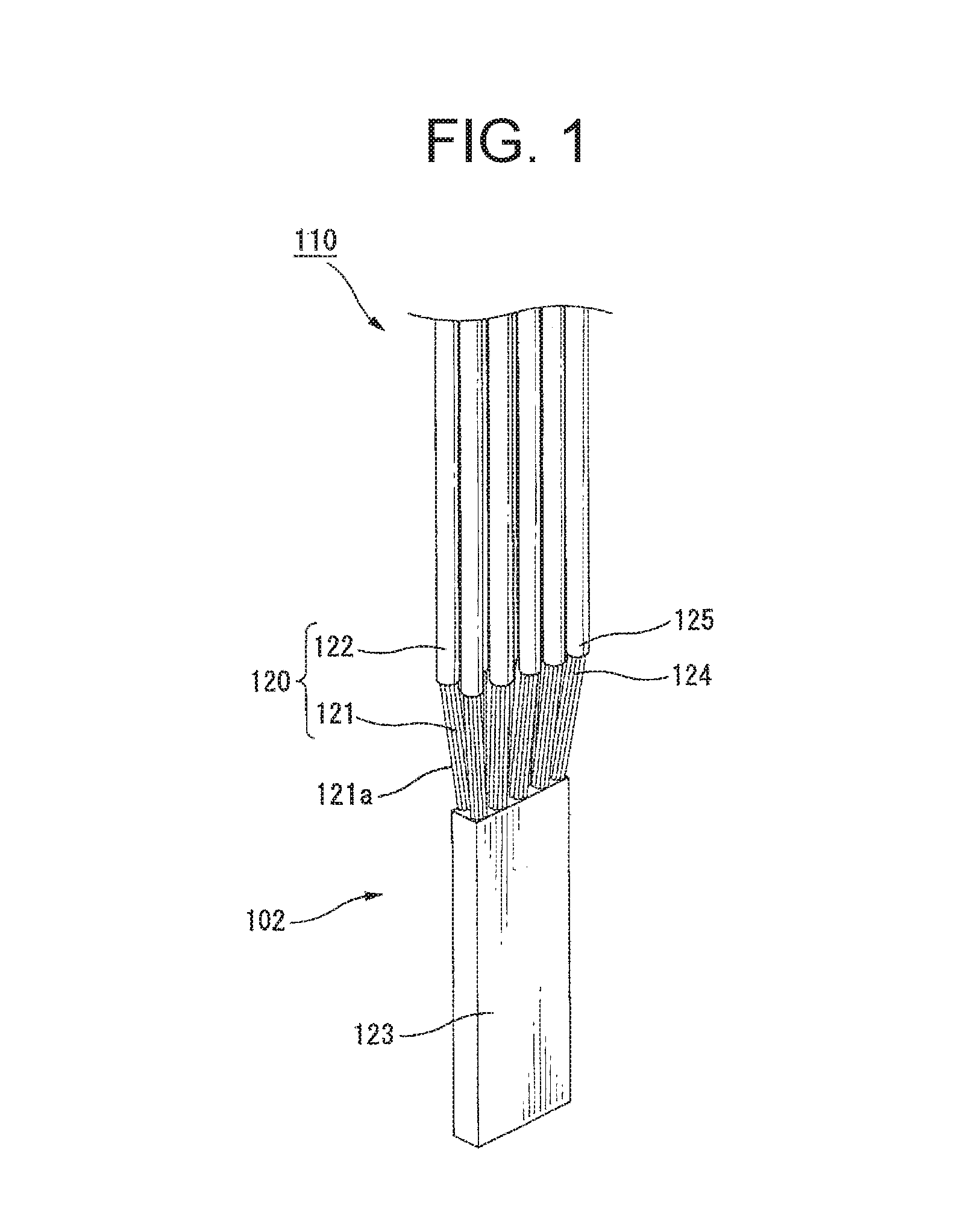
[0321]Based on the content described above, we tried to produce the cable 401 applicable to an automobile wire harness (for example, the wire harness 407). First, as shown in FIG. 15, the core wire 410 made of a plurality of element wires 411 and applicable to an automobile wire harness is prepared.

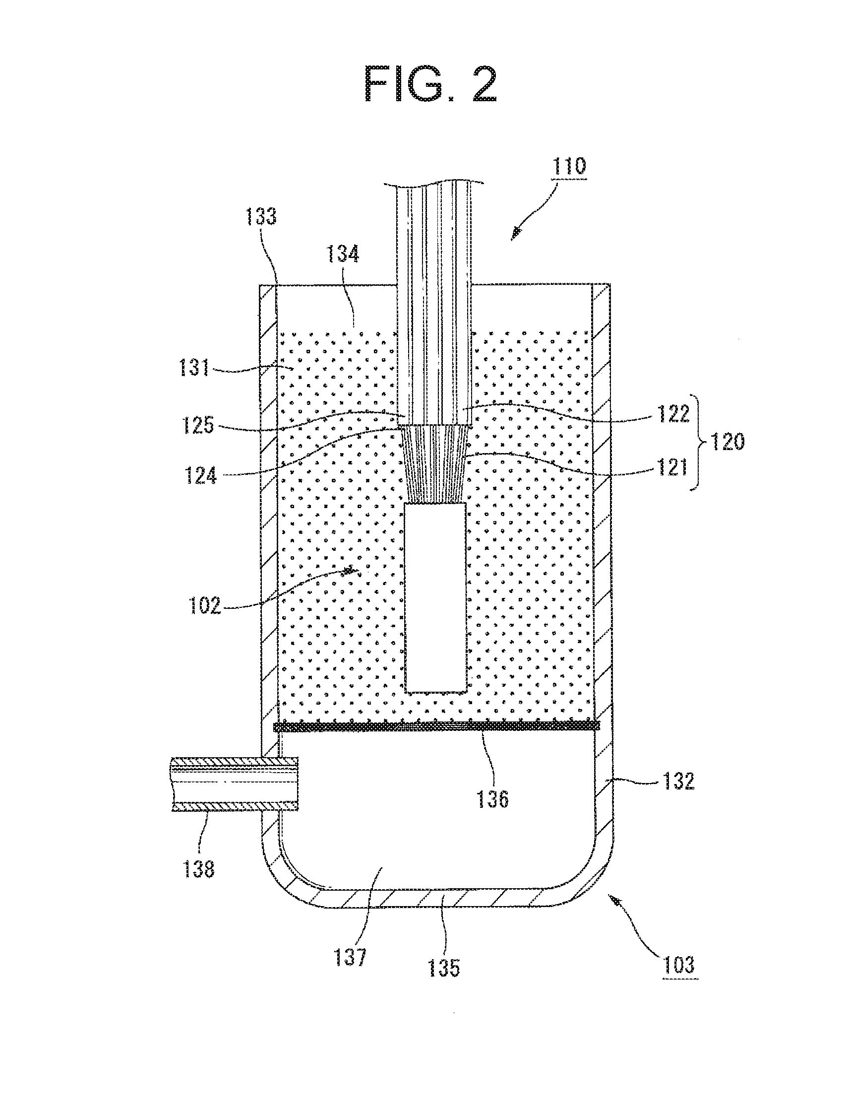
[0322]Next, the coating target region 413 is heated up to about 120° C. by induction heating by passing an alternating current to the heating coil portion 660 of the induction heating unit 606 positioned on the outer circumferential side of the immersion container 403 while the coating target region 413 of the core wire 410 is immersed in the powder material 431 inside the immersion container 403 as shown in FIG. 30 and the heated state is maintained for about 30 sec. Incidentally, a material using a polyamide thermoplastic resin (Platamid manufactured by Arkema, product number: HX2544PRA170) and pulverized to about 80 μm t...

example 2

According to the Third Mode of the Method of Manufacturing a Cable

[0325]Next, the core wire 410 applicable to an automobile wire harness (for example, the wire harness 407) and having the branching portion 414 as shown in FIGS. 19, 34, 35, and 37 is prepared and the production of the cable 401 in such a branching shape is tried. First, as shown in FIGS. 34 and 35, like in Example 1, the coating target region 413 is heated up to about 120° C. by induction heating while the coating target region 413 of the core wire 410 is immersed in the powder material 431 inside the immersion container 403 and the heated state is maintained for about 30 sec. The powder material 431 similar to that in Example 1 is applied.

[0326]Then, the observation of the coating target region 413 taken out of the immersion portion 434 shows that the melt of the powder material 431 adheres like covering the coating target region 413 and the melt is set after the temperature thereof drops to form the coating portion...


PUM


Abstract

To provide a method of manufacturing a cable when the cable is obtained by coating a core wire and a method of manufacturing a composite electric wire. To coat an outer circumferential side of a core wire or a plurality of bundled core wires with a coating portion made of an insulating polymeric material, first any exposure target region of the core wire is held below a melting temperature of the insulating polymeric material and a coating target region of the core wire positioned outside the exposure target region is heated to the melting temperature of a powder material (insulating polymeric material in a powder state). Then, the coating portion is formed by immersing the core wire of the coating target region having been heated in the powder material inside an immersion container to allow the insulating polymeric material to adhere to the core wire of the coating target region.

Description

BACKGROUND[0001]1. Technical Field[0002]The present invention relates to a method of manufacturing a cable and a method of manufacturing a composite electric wire, and for example, relates to an electric wire applicable to an automobile wire harness.[0003]2. Related Art[0004]A cable used for a composite electric wire, for example, an automobile wire harness and the like has a configuration in which an outer circumferential side of a core wire (for example, a core wire formed by using one or more wire-shaped or stranded metallic wires) is coated with a coating portion (coating portion made of an insulating polymeric material or the like) and can be produced by the general powder coating method, but in recent years, from the viewpoint of mass production and the like, is produced mainly by extrusion molding, for example, in a form that can be stored by winding like a coil using a long cable (see, for example, JP 560-36046 B and JP 2002-343164 A).[0005]In the case of a composite electri...

Claims


Application Information

Patent Timeline
IPC IPC(8): H01B13/16H01B13/00
CPCH01B13/0016H01B13/16H01B13/06H01B13/22H01B13/30H01B13/32H01B13/321H01B7/28H02G1/14H02G15/04H02G15/08
Inventor MUKAIYAMA, HIROKIMATSUOKA, SYOGOIKEGAYA, KAZUYAHORIUCHI, SATORUKAGAMI, KAZUYOSHI
Owner YAZAKI CORP
Why Eureka
Try Eureka