

Treatment of release layer
a technology of release layer and release layer, which is applied in the direction of printing, duplicating/marking methods, and other printing apparatus, can solve the problems of direct ink jetting of liquid inks, aqueous, and process drawbacks, and achieve the effect of improving the quality of liquid inks, reducing the risk of contamination, and reducing the safety and environmental concerns
- Summary
- Abstract
- Description
- Claims
- Application Information
AI Technical Summary
Benefits of technology
Problems solved by technology
Method used
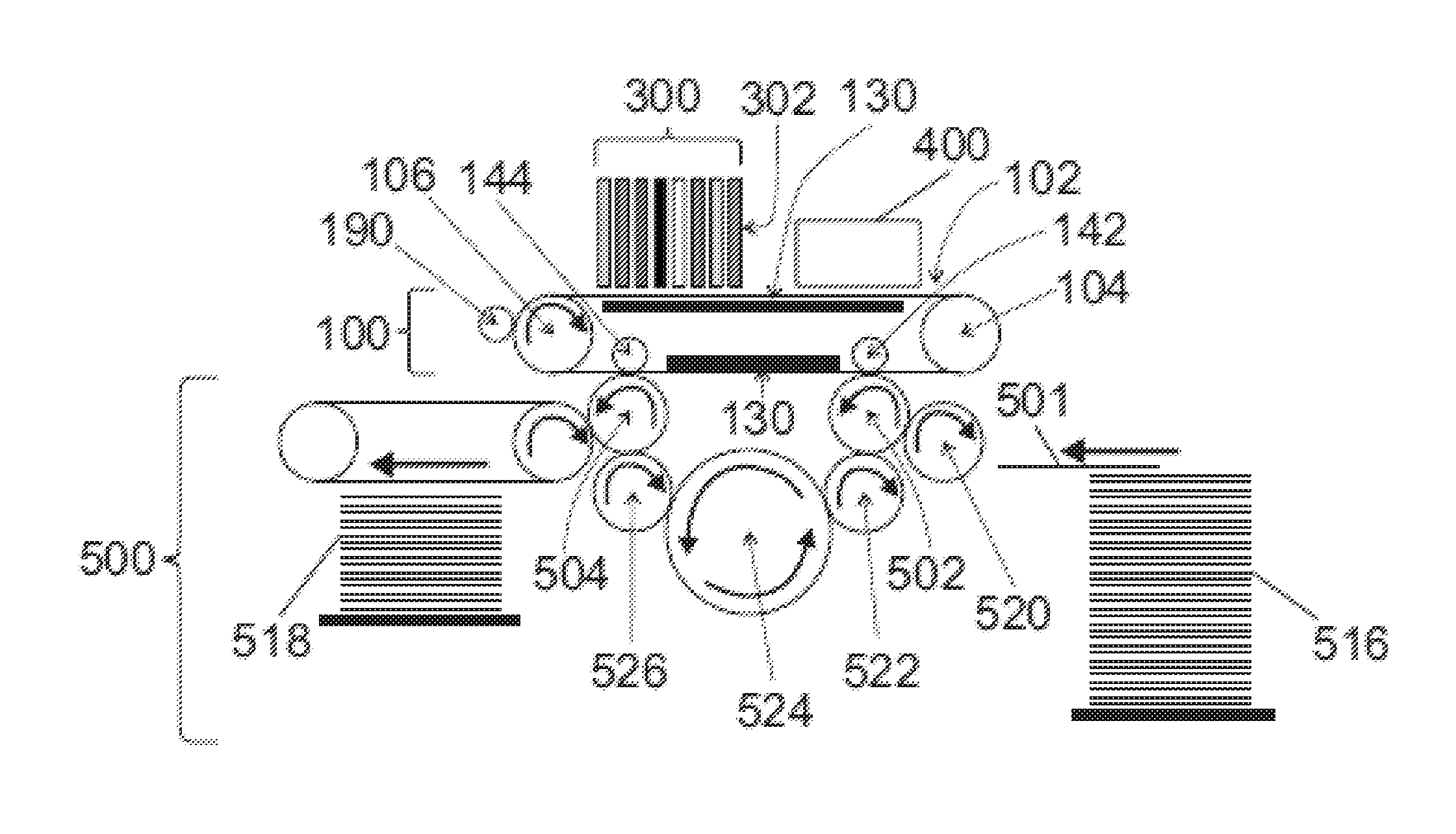
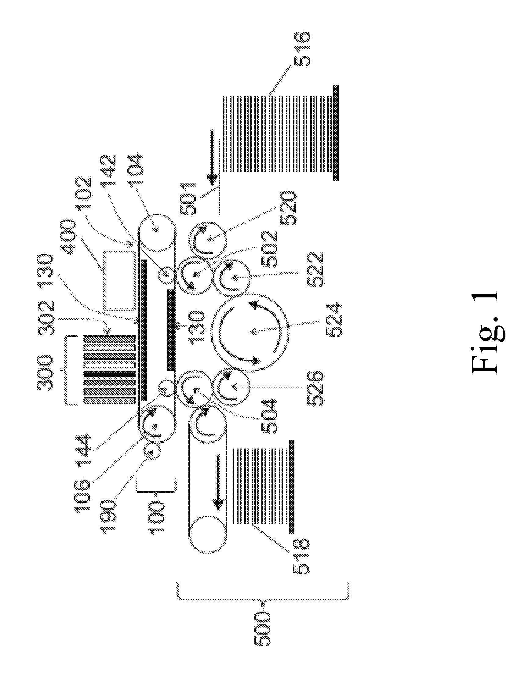
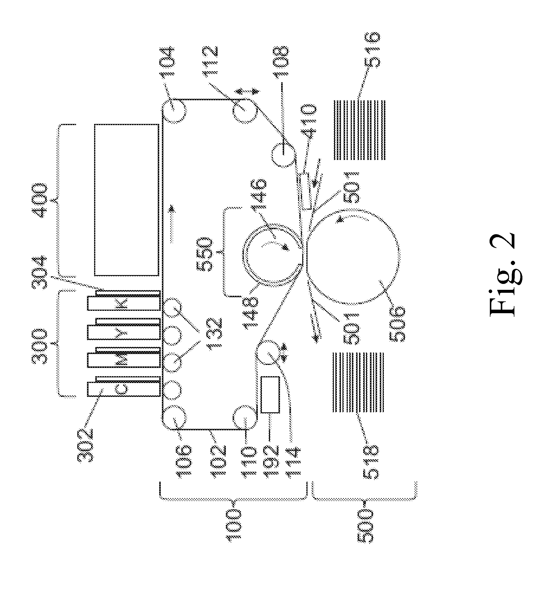
Image

Examples
example 1
[0151]An inkjet ink formulation was prepared containing:
IngredientFunctionwt. %Carbon Black, Monarch ®Pigment1.5700 (Cabot)Joncryl ® 2038, 43.5%Resin13.8emulsion in water(6% solids)Tween ® 40Softening agent3.0Capstone FS-65 (DuPont)Non-ionic fluorosurfactant 0.01Water—Balanceto 100%Joncryl HPD 296 (35.5%Dispersant4.2water solution) (BASF)(solid resin)Ethylene glycol (Aldrich)Water-miscible co-solvent15
[0152]Preparation procedure: A pigment concentrate, containing pigment (14%), water (79%) and Joncryl® HPD 296 (7%) were mixed and milled using a homemade milling machine. The progress of milling was controlled by particle size measurement (Malvern, Nanosizer). The milling stopped when the particle size (D50) reached 70 nm. Then the rest of the materials were added to the pigment concentrate. After mixing the ink was filtered through 0.5 micrometer filter.
[0153]The efficacy of various materials in improving the transfer of the black ink formulation described above were tested as foll...
example 2
[0158]Example 1 was repeated, but this time the surface of the CCRL PDMS release layer, instead of being spread with a thin film of ink, was printed with drops of ink of 9 picoliter drop size, using a Fujifilm Dimatix DMP-2800 printer (www.fujifilmusa.com / products / industrial_inkjet_printheads / deposition-products / dmp-2800 / index.html). Again, beading of the ink on the treated release layer surface was not observed, and results similar to those in Example 1 were obtained for both the PEI and amine functionalized silicone (SOL1 comprising about 1 wt. % of GP-4) treatments, for both coated and uncoated paper as above-identified.
example 3
[0159]Example 1 was repeated, but this time SOL4 (comprising about 2 wt. % GP-965) was used to treat the CCRL PDMS release layer instead of SOL1. A continuous shiny film was obtained on the coated paper for both the PEI and amine functionalized silicone treatments. Beading of the ink on the treated release layer surface was not observed. Printing on the uncoated paper showed that transfer from the PEI-coated portion of the release layer was not complete, but transfer from the GP-965-coated portion was complete.
PUM
| Property | Measurement | Unit |
|---|---|---|
| Temperature | aaaaa | aaaaa |
| Temperature | aaaaa | aaaaa |
| Temperature | aaaaa | aaaaa |
Abstract
Description
Claims
Application Information