Downhole Optical Communication

a technology of optical communication and downhole, applied in the field of relativly high bandwidth optical communication, can solve the problems of unreliable conventional techniques and very impractical optical telemetry

Active Publication Date: 2016-07-21
HALLIBURTON ENERGY SERVICES INC
View PDF13 Cites 13 Cited by
  • Summary
  • Abstract
  • Description
  • Claims
  • Application Information

AI Technical Summary

Problems solved by technology

High temperatures (for example, ˜200 deg. C. and above) and long distances (for example, ˜3 km and more) can make optical telemetry very impractical and / or unreliable using conventional techniques.

Method used


Image

  • Downhole Optical Communication
  • Downhole Optical Communication
  • Downhole Optical Communication

Examples


Embodiment Construction

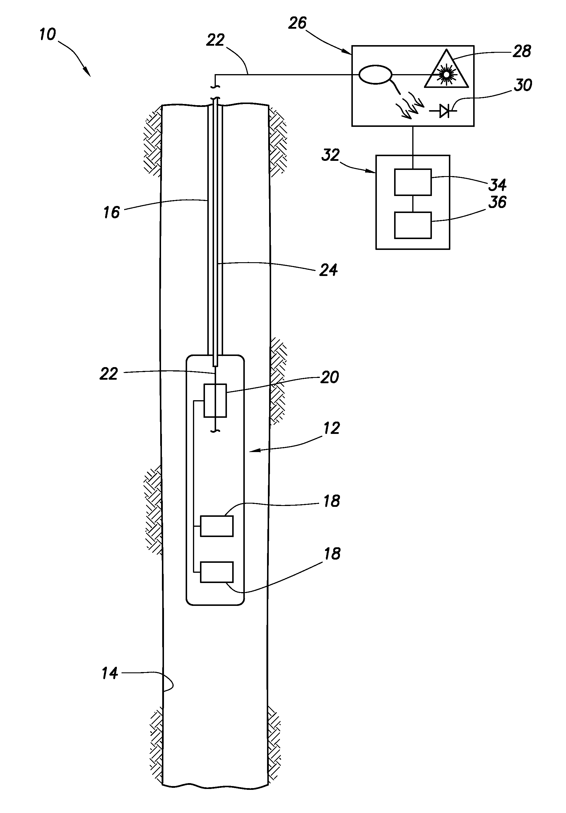
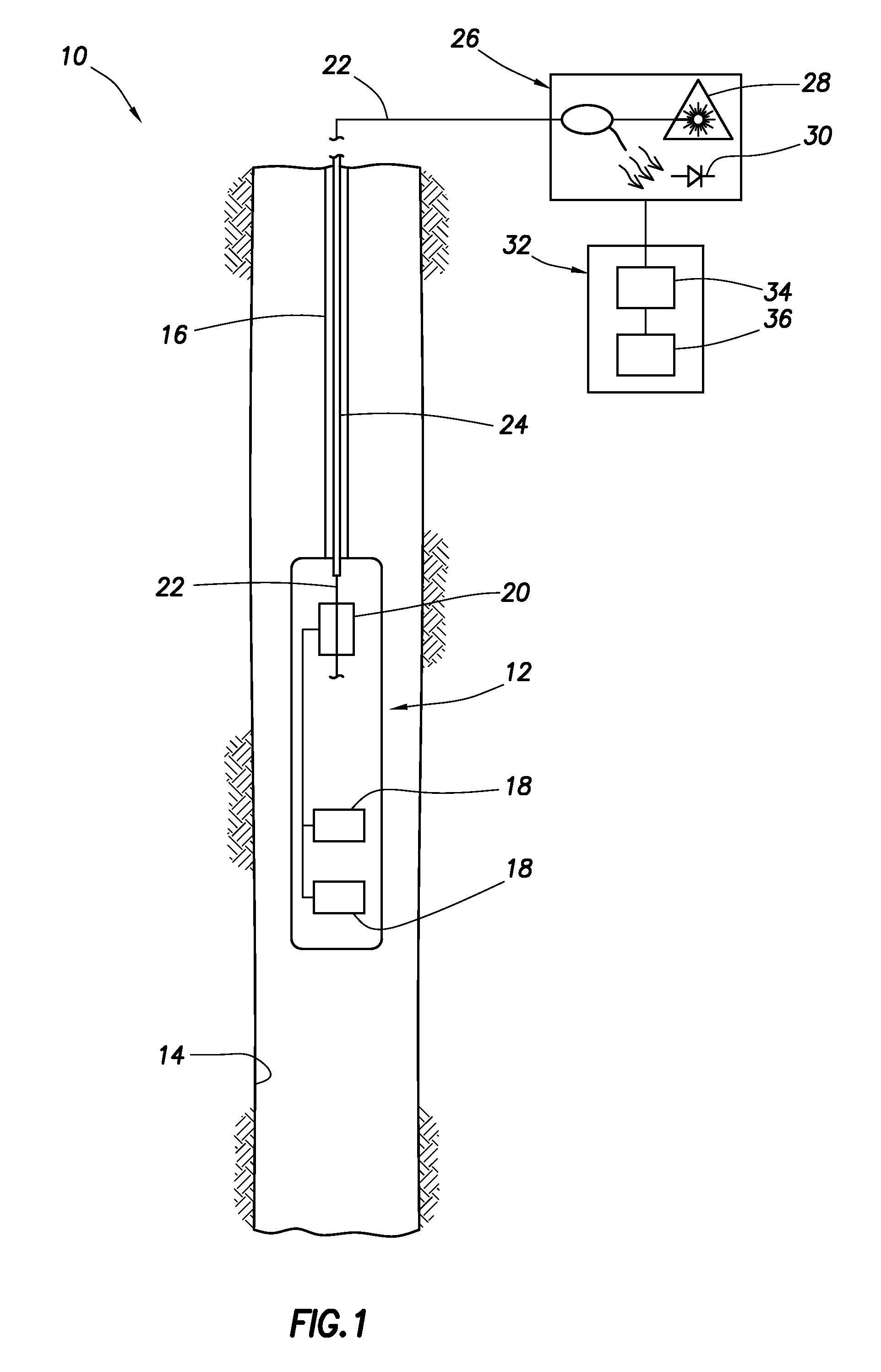
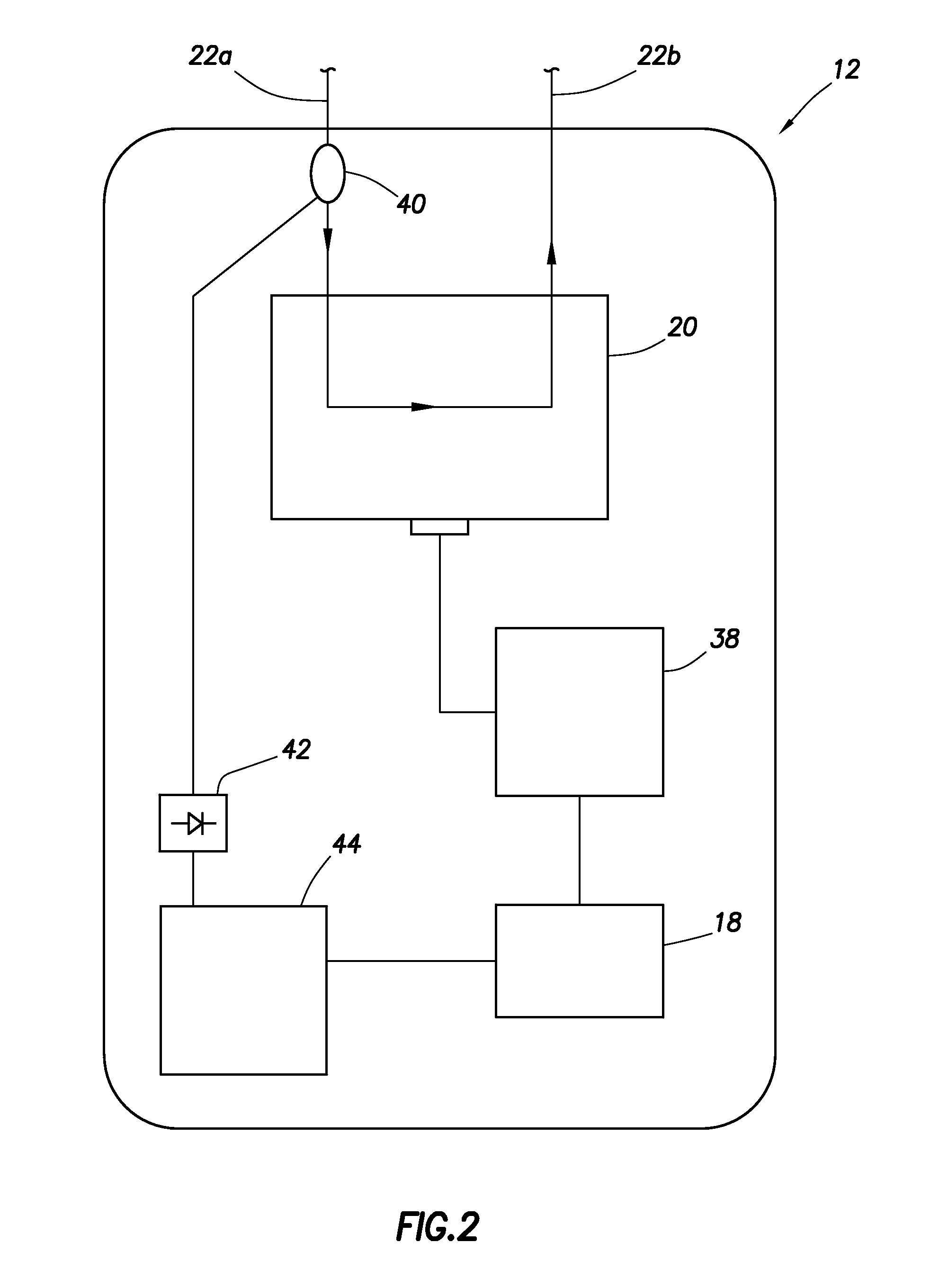
[0009]In one example, this specification is directed to high speed fiber optic communication systems, and methods for communication between a remote location (such as, a surface location, a subsea facility, a floating rig, etc.) and one or more downhole tools / instruments, using only passive (unpowered) optical components deployed downhole, other than an optical modulator. The downhole tool or instrument may be attached to a wireline cable, slickline, coiled tubing, or any other downhole tool conveyance method where a fiber optic cable may be deployed.

[0010]Coherent phase light can be used in examples described below, although coherency is not strictly necessary in all examples. Waveguides other than optical “fibers” may be used in examples described herein.

[0011]This specification provides several methods for high speed telemetry to and from downhole tools using optical telemetry over one or more optical waveguides. Single-mode fiber may be preferred for most configurations, but mul...


PUM


Abstract

A method of optical communication in a well can include launching light having substantially coherent phase into an optical waveguide extending in a wellbore, modulating light having substantially coherent phase in the wellbore, and receiving the modulated light transmitted via the same optical waveguide. A well system can include at least one optical waveguide extending in a wellbore, and a downhole optical modulator which modulates light transmitted via the optical waveguide, the optical modulator comprising a potassium titanyl phosphate crystal. Another method of optical communication in a well can include launching light into an optical waveguide extending in a wellbore, the light launched into the optical waveguide having information modulated thereon using a carrier, modulating light in the wellbore, the modulating comprising modulating information using a subcarrier of the carrier, and transmitting the light modulated in the wellbore via the same optical waveguide.

Description

TECHNICAL FIELD[0001]This disclosure relates generally to operations performed and equipment utilized in conjunction with a subterranean well and, in one example described below, more particularly provides for relatively high bandwidth optical communication in wells.BACKGROUND[0002]High temperatures (for example, ˜200 deg. C. and above) and long distances (for example, ˜3 km and more) can make optical telemetry very impractical and / or unreliable using conventional techniques. For these reasons and others, it will be appreciated that improvements are continually needed in the art of downhole optical communication. Such improvements may be useful whether or not the optical communication is performed at relatively high temperatures or over relatively long distances.BRIEF DESCRIPTION OF THE DRAWINGS[0003]FIG. 1 is a representative partially cross-sectional view of a well system and associated method which can embody principles of this disclosure.[0004]FIG. 2 is a representative schemati...

Claims


Application Information

Patent Timeline
Patent Type & Authority Applications(United States)
IPC IPC(8): E21B47/12H04B10/516H04B10/25
CPCE21B47/123H04B10/5161H04B10/2504E21B47/135H04B10/2587H04B10/25891
Inventor BARFOOT, DAVID AMAIDA, JR., JOHN L.SAMSON, ETIENNE M.
Owner HALLIBURTON ENERGY SERVICES INC
Why Eureka
Try Eureka