Underground heat-exchange system

a heat exchange system and heat exchange technology, applied in the field of underground heat exchange systems, can solve the problems of affecting water quality, polluting the atmosphere, wind, solar and geothermal energy sources, though unlimited in quantity, and not reaching the energy density to substitute fossil fuels, etc., to achieve the effect of improving the efficiency of energy consumption, reducing management and maintenance costs, and improving energy consumption

Active Publication Date: 2016-07-21
UNIV OF SEOUL IND COOP FOUND
View PDF5 Cites 6 Cited by
  • Summary
  • Abstract
  • Description
  • Claims
  • Application Information

AI Technical Summary

Benefits of technology

[0034]An underground heat exchange system according to an embodiment of the present invention offers technical advantages, including improving efficiency of energy consumption required for circulating a heat transfer medium, and reducing management and maintenance costs by natural circulation that makes use of the height difference caused by the position of a medium collector to induce the heat transfer medium to circulate.
[0035]Furthermore, the underground heat exchange system according to the embodiment of the present invention offers technical advantages, including making construction easy and improving heat exchange efficiency with the use of a flow rate reducing means or collision members for creating a vortex, because the underground heat exchange system includes a double-pipe heat exchanger and its outer tip is wedge- or dome-shaped.
[0036]In addition, the underground heat exchange system according to the embodiment of the present invention offers technical advantages, including automating a series of operations and quickly coping with emergency situations such as breakdowns by including a water level sensor, an upstream pump, an on-off valve, and a controller for allowing the water level sensor, the upstream pump, and the on-off valve to work in conjunction with one another.

Problems solved by technology

Fossil fuels, and electricity generated by fossil fuels or nuclear power, are materials most commonly used for heating, cooling, and power generation, but emissions from the burning of fossil fuels are harming water quality and polluting the atmosphere, and because our limited resources are being depleted, there is an urgent need for the development of alternative energy sources.
However, there is a problem in that the wind, solar, and geothermal energy sources, though unlimited in quantity, still have not reached sufficient energy density to substitute for fossil fuels.
For example, wind and solar power installations are subject to location constraints to harvest as much energy as needed, and are also subject to preconditions such as securing a unit area of a certain size or larger.
In addition, even if these preconditions are met, ensuring energy production is difficult due to environmental factors and the costs of installation, maintenance, and management are high.
However, the heat exchanger pipes, if formed to extend linearly, are limited in their contact area or time for heat exchange with the ground, thus decreasing heat exchange efficiency.
Although the conventional art may enhance, in part, the heat exchange efficiency of the heat transfer medium using geothermal heat, it cannot prevent energy waste caused by forcing the circulation of the heat transfer medium for heat exchange.
In particular, the ground heat exchanger according to the conventional art is constructed in the form of a pipe that bent at predetermined intervals in order to increase the contact area and time for heat exchange and this increases preliminary work for construction, such as excavation, thus resulting in high construction costs.

Method used


Image

  • Underground heat-exchange system
  • Underground heat-exchange system
  • Underground heat-exchange system

Examples


Embodiment Construction

[0043]Hereinafter, the technical configuration of an underground heat exchange system according to an exemplary embodiment of the present invention will be described in detail with reference to the attached drawings.

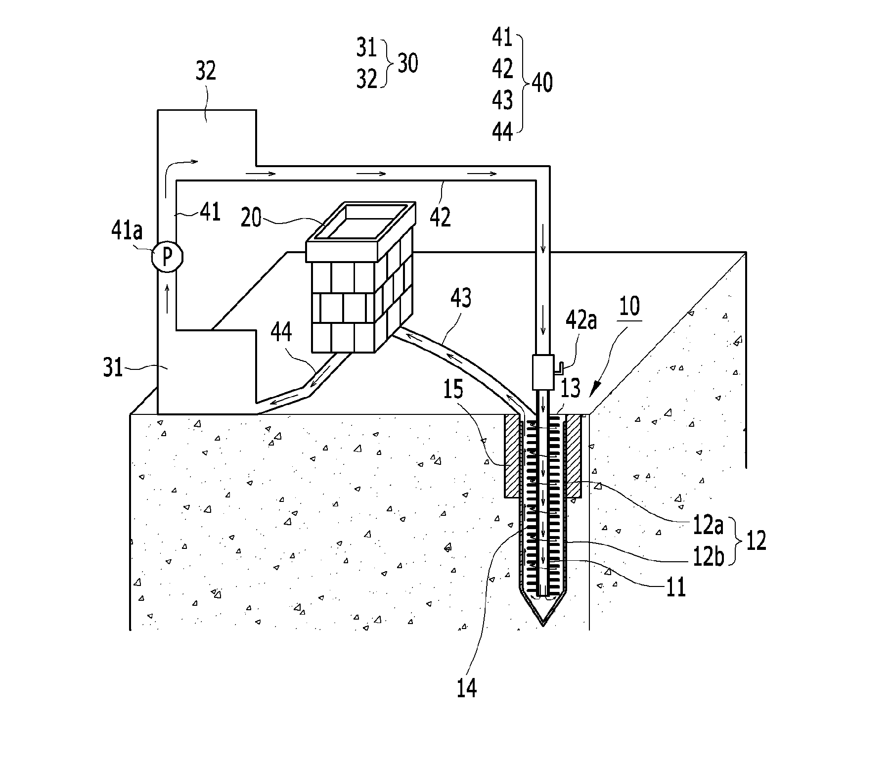
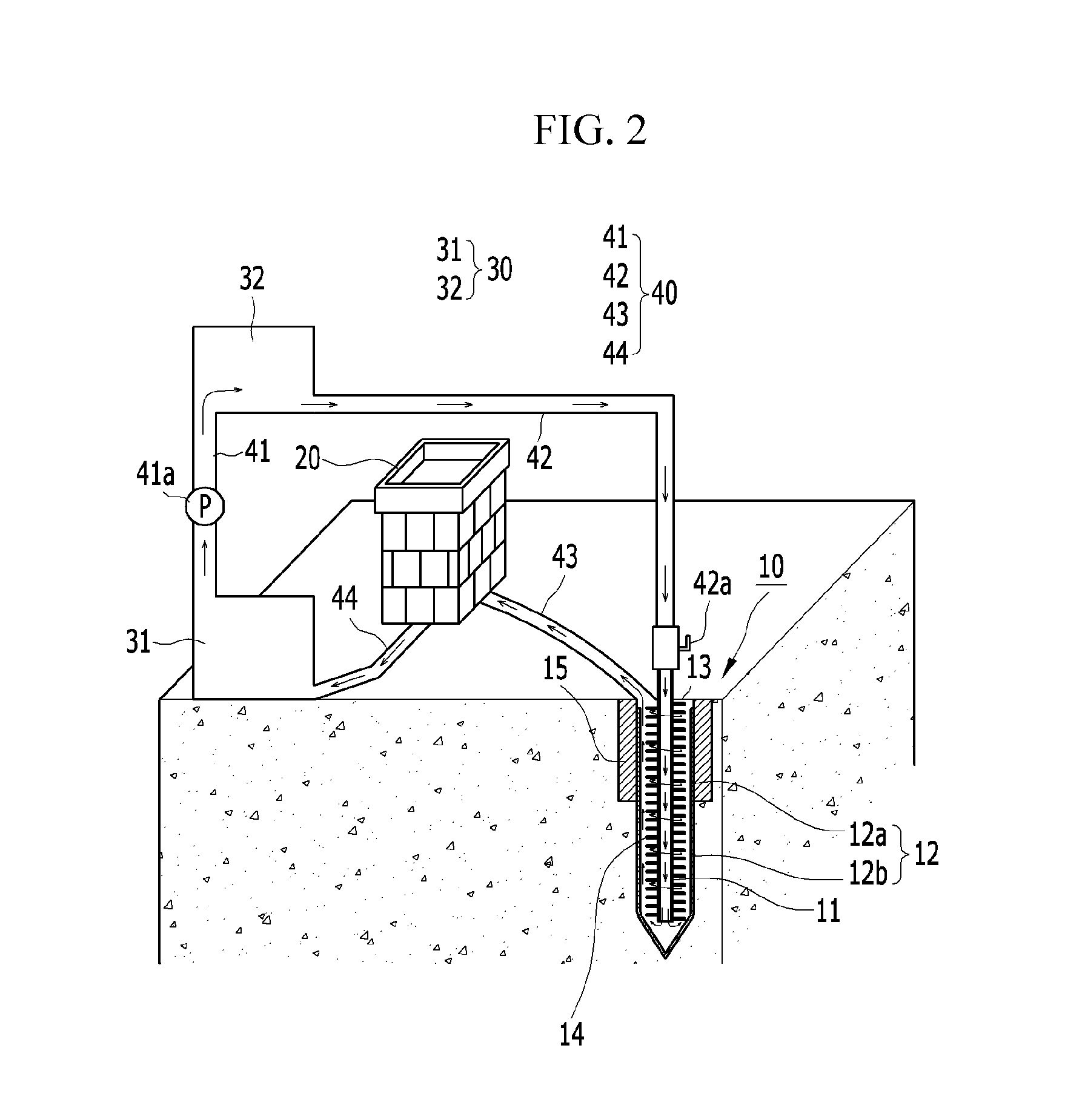
[0044]First, as illustrated in FIG. 2, the underground heat exchange system according to the exemplary embodiment of the present invention includes a ground heat exchanger 10 for converting a heat transfer medium into a usable form, a heat consumption area 20, and a medium collector 30 that collects the heat transfer medium that has dispersed its heat via the heat consumption area 20.

[0045]A circulation loop 40 is provided among the ground heat exchanger 10, heat consumption area 20, and medium collector 30 to form a closed loop for circulating the heat transfer medium.

[0046]The ground heat exchanger 10 has a double-pipe structure that is buried underground, which allows for smooth heat transfer between the heat transfer medium and the ground.

[0047]The medium collector 3...


PUM


Abstract

An underground heat exchange system is provided to reduce energy consumption for circulation of a heat transfer medium and reduce construction, management, and maintenance costs. The underground heat exchange system includes: a double-pipe heat exchanger that is buried underground to convert a heat transfer medium into a usable form; a medium collector that collects the heat transfer medium that has dispersed its heat via a heat consumption area to circulate the same to the ground heat exchanger; and a plurality of circulation loops. The medium collector includes first and second reservoirs that are arranged in two tiers: upper and lower, spaced apart from each other, an upstream pump is provided in a first circulation loop between the first and second reservoirs, and the second reservoir is placed higher than the first reservoir. The ground heat exchanger may enhance heat exchange efficiency by increasing the contact area and time between the ground and the heat transfer medium.

Description

CROSS-REFERENCE TO RELATED APPLICATION[0001]This application claims priority to and the benefit of Korean Patent Application No. 10-2013-0119689 filed in the Korean Intellectual Property Office on Oct. 8, 2013, the entire contents of which are incorporated herein by reference.BACKGROUND OF THE INVENTION[0002](a) Field of the Invention[0003]The present invention relates to an underground heat exchange system, and more particularly, to an underground heat exchange system capable of reducing energy consumption for operating the underground heat exchange system by dividing a medium collector storing a heat transfer medium into a plurality of parts with different installation heights and inducing the heat transfer medium to circulate by potential energy of the medium collector.[0004](b) Description of the Related Art[0005]Fossil fuels, and electricity generated by fossil fuels or nuclear power, are materials most commonly used for heating, cooling, and power generation, but emissions fro...

Claims


Application Information

Patent Timeline
Patent Type & Authority Applications(United States)
IPC IPC(8): F24J3/08
CPCF24J3/081F24J2003/087F24J2003/089F28F1/34F28F2215/10F24T10/17F24T2010/50F24T2010/56Y02E10/10F24T10/10
Inventor YU, BYUNG DEOKMIN, HYUNSOOJEON, JUNJIN
Owner UNIV OF SEOUL IND COOP FOUND
Why Eureka
Try Eureka