Image display device in the form of a pair of eye glasses

Active Publication Date: 2016-07-21
CY VISION INC
View PDF0 Cites 21 Cited by
  • Summary
  • Abstract
  • Description
  • Claims
  • Application Information

AI Technical Summary

Benefits of technology

[0008](i) Eliminating the relay optics between the spatial light modulator and eye. The focusing problem of the eyes is overcome using the pinhole display principle, which provides infinite depth of focus. As a result, miniaturization of wearable displays will be possible by taking full advantage of the advancement

Problems solved by technology

There are many wearable technologies that deliver a virtual image to the eye but they all require relay lenses between the display panel and the eye.
In the state of the art embodiments, there are some examples of head-mounted displays in military HMD's and virtual reality goggles with large FOV (up to 80° or 120°) but the optics are very bulky.
Alternative approaches to reduce the size and bulk of the optics have exploited different solutions: (i) Active pupil-tracking is a promising solution but the optical mechanisms offered to track the pupil are quite complicated; (ii) Unconventional optical relays to make the optics more compact using light guides relays, holographic relays, or substrate guided relays, which are promising but still require a compromise in FOV to achieve the thin form-factor; (iii) Displays that require wearing a special contact lens.
Viewing the display requires a special conta

Method used


Image

  • Image display device in the form of a pair of eye glasses
  • Image display device in the form of a pair of eye glasses
  • Image display device in the form of a pair of eye glasses

Examples


Example

REFERENCE NUMERALS

[0020]1. Image display device[0021]2. Spatial light modulator[0022]3. Point light source[0023]3A. Aperture[0024]3B. Camera[0025]4. Micro reflector[0026]5. Filter[0027]6. Frame[0028]7. Nose bridge[0029]8. Pupil tracker camera[0030]9. interface cables[0031]10. Exit pupil replicator

DETAILED DESCRIPTION OF THE INVENTION

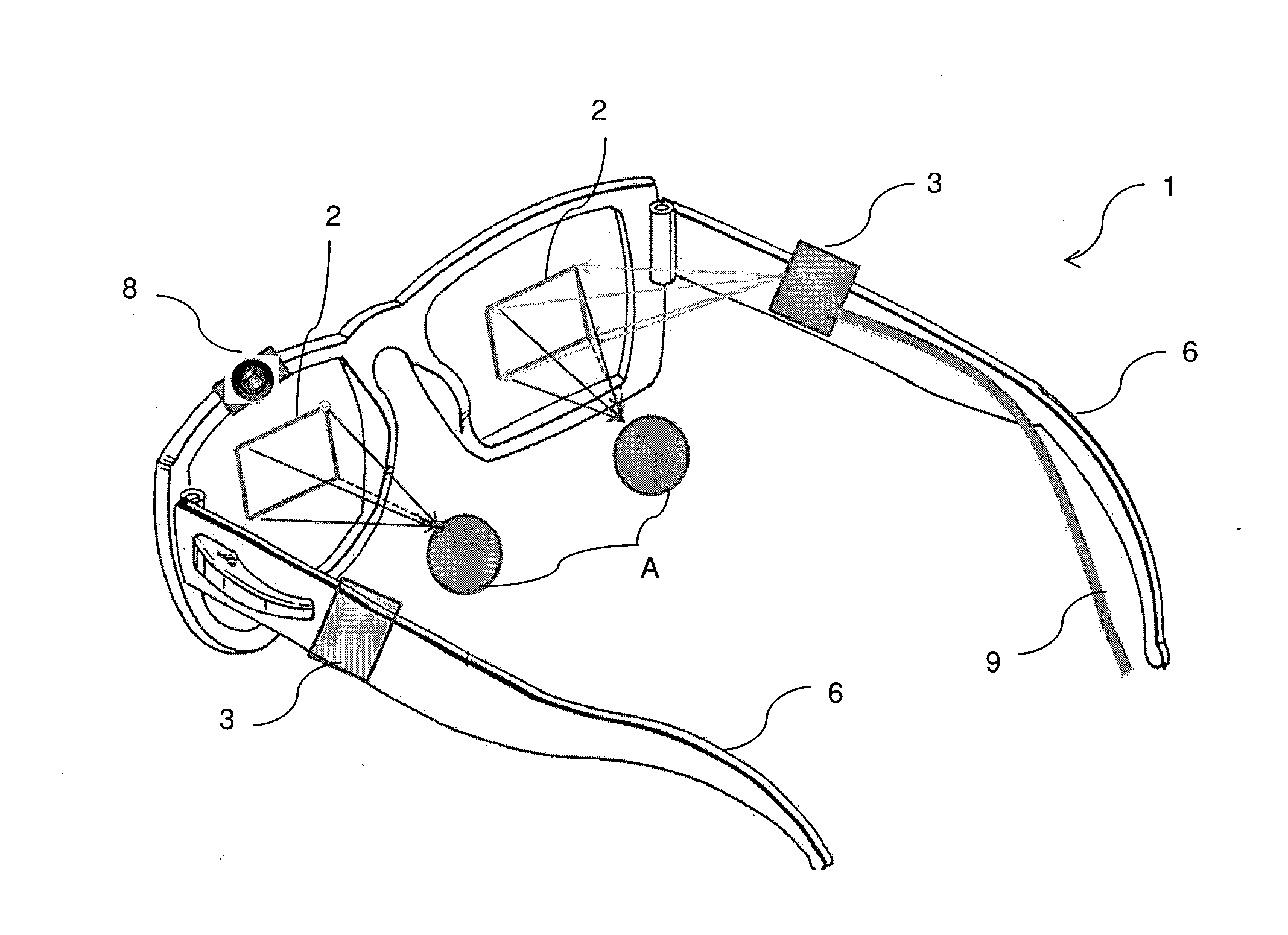
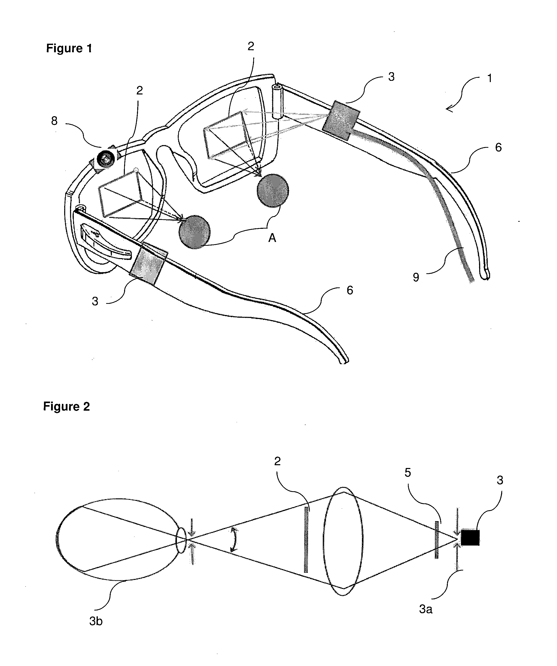
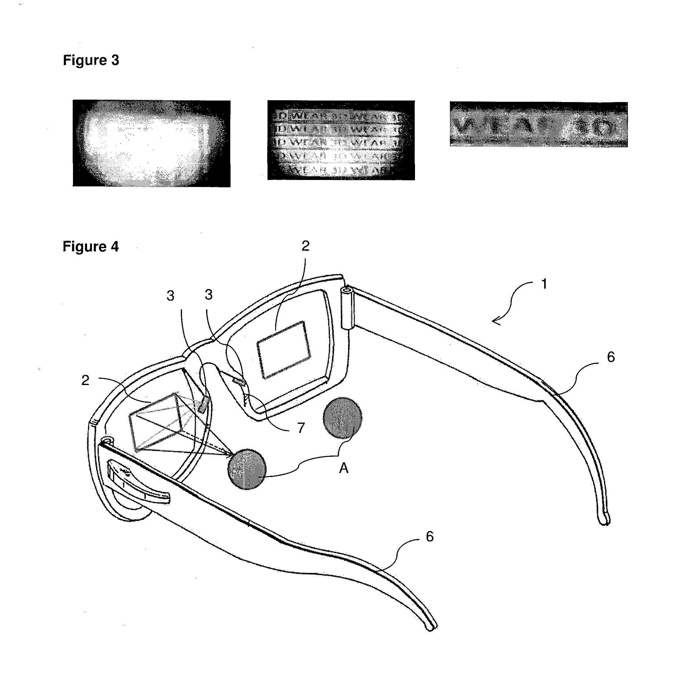
[0032]The image display device (1) of the present invention comprises at least one spatial light modulator (2), at least one point light source (3), wherein the point light source (3) and the viewer's eyes (A) are placed on the front side of the spatial light modulator (SLM) (2) such that the point light source (3) directly illuminate the front surface of the spatial light modulator (2) and characterized by a matrix of micro reflectors (4) that are attached on the back surface of the spatial light modulator (2).

[0033]Referring to FIG. 1, the basis of this invention is the pinhole camera imaging principle. The pinhole based imaging principle disclosed in ...


PUM


Abstract

The present invention relates to an image display device (1) comprises at least one spatial light modulator (2), at least one point light source (3), wherein the light source (3) is placed in front of the spatial light modulator (2). The display device is suitable for wearable Augmented Reality (AR) and 3D displays.

Description

TECHNICAL FIELD[0001]The present invention relates to an image display device and more particularly, to a wearable image display device in the form of a pair of eye glasses.BACKGROUND[0002]Wearable displays are an enabling technology for Virtual Reality (VR), Augmented Reality (AR), and 3D mobile displays. There are many wearable technologies that deliver a virtual image to the eye but they all require relay lenses between the display panel and the eye.[0003]In the design of wearable displays, it is desired to have a large field-of-view (FOV) and a large exit-pupil-size (12-15 mm) to allow for eye-motion without losing the image. In the state of the art embodiments, there are some examples of head-mounted displays in military HMD's and virtual reality goggles with large FOV (up to 80° or 120°) but the optics are very bulky. Alternative approaches to reduce the size and bulk of the optics have exploited different solutions: (i) Active pupil-tracking is a promising solution but the op...

Claims


Application Information

Patent Timeline
IPC IPC(8): G02B27/01G02B26/02G02B27/00G02B5/09G02F1/1335
CPCG02B27/0172G02B5/09G02F1/133555G02B2027/0118G02B26/02G02B2027/0178G02B2027/0123G02B27/0093G02B27/017G02B2027/0127G02B2027/0187
Inventor UREY, HAKAN
Owner CY VISION INC
Why Eureka
Try Eureka