
Method for performing peak clipping to multiple carrier waves and device thereof

Active Publication Date: 2016-07-21
DATANG MOBILE COMM EQUIP CO LTD
View PDF4 Cites 9 Cited by
  • Summary
  • Abstract
  • Description
  • Claims
  • Application Information

AI Technical Summary

Benefits of technology

The patent describes a method for generating a digital filter to peak clip signals in a wireless communication system. The method is designed to maximize the use of the available bandwidth and reduce distortion and error in the signals. This is achieved by using a single peak clipping coefficient for multiple carrier waves, which simplifies the generation process and reduces the impact of distortion and error on the signal quality. Overall, this method improves the efficiency and quality of wireless communication systems.

Problems solved by technology

In the multi-carrier wave cells, the multi-carrier wave signals that need to be transmitted perform linear superposition and combinations in the digital intermediate frequency section, and share a common set of transmitters to transmit, therefore, the transmitting end of the antenna appears higher PAR (Peak to Average Ratio) signals, and this requires the power amplifier to have larger linear regions, thus leading to lower efficiencies of the power amplifier, and then causing increased cost of the power amplifier.
However, the peak clipping coefficient obtained in this way is too complex, and each peak clipping coefficient is obtained by adding up multiple basic prototype coefficients, making EVM (Error Vector Magnitude) of the signal increased after the peak clipping.
Especially, in the conventional technologies, with the increment of number of earlier waves and the expanding of frequency band, the system bandwidth needed is wider and wider, and at that moment, the added up prototype coefficients are more, the calculation of the peak clipping coefficient is also more complex, thus making EVM of the signal even more serious after the peak clipping, and then causing the signal distortion more serious.

Method used


Image

  • Method for performing peak clipping to multiple carrier waves and device thereof
  • Method for performing peak clipping to multiple carrier waves and device thereof
  • Method for performing peak clipping to multiple carrier waves and device thereof

Examples


first embodiment

The First Embodiment

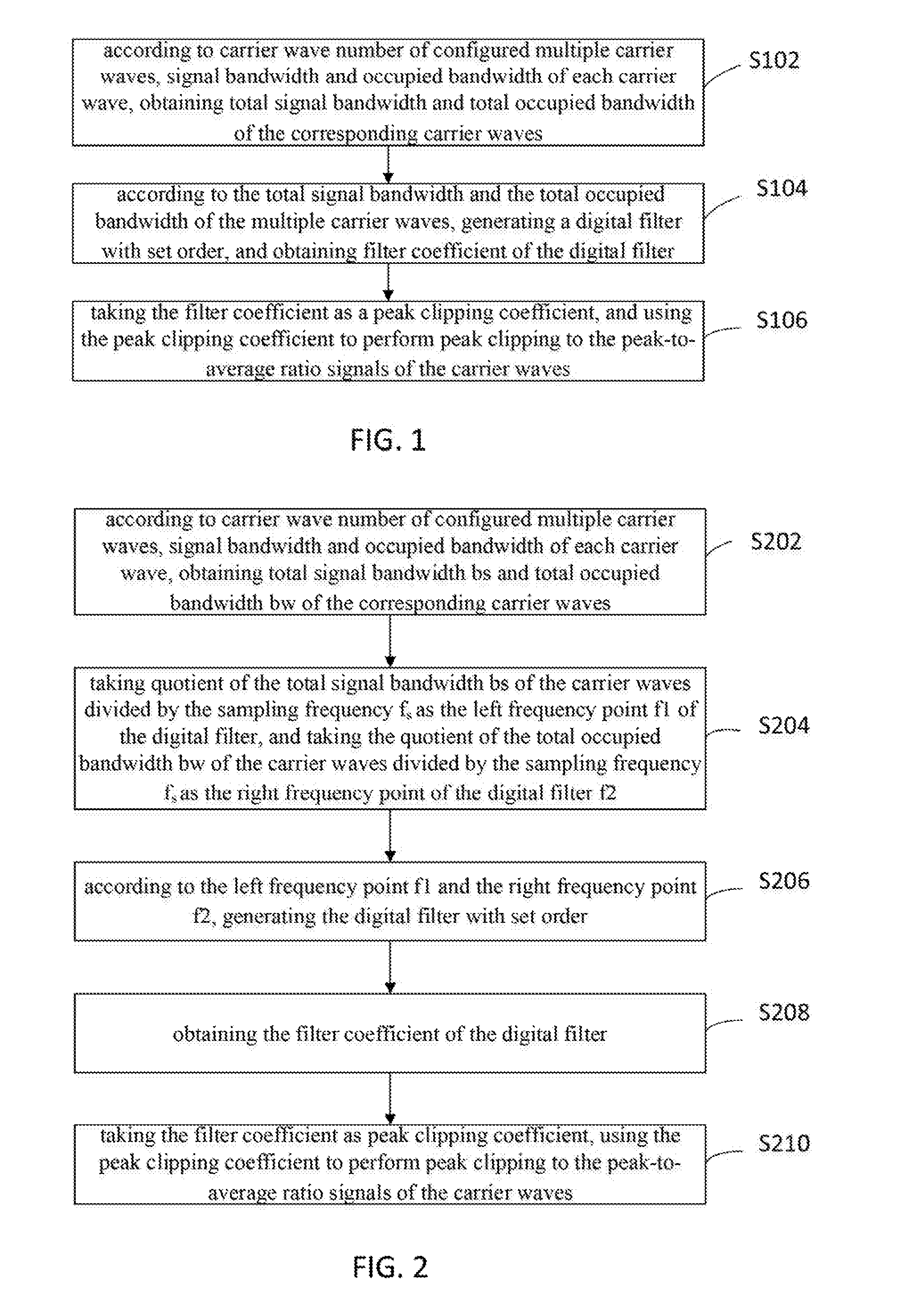
[0050]With reference to FIG. 1, it shows is a flowchart showing steps of a method for performing peak clipping to multiple carrier waves according to the first embodiment of the disclosure.

[0051]The method for performing peak clipping to multiple carrier waves includes the steps of:

[0052]Step S102, according to carrier wave number of configured multiple carrier waves, signal bandwidth and occupied bandwidth of each carrier wave, obtaining total signal bandwidth and total occupied bandwidth of the corresponding carrier waves;

[0053]The signal bandwidth refers to the width of signal frequency spectrum, that is, the difference between the maximum frequency component and the minimum frequency component, the occupied bandwidth is the occupied bandwidth of the energy (power) transmitted from the channel.

[0054]Step S104, according to the total signal bandwidth and the total occupied bandwidth of the multiple carrier waves, generating a digital filter with set order, and ...

second embodiment

The Second Embodiment

[0059]As shown in FIG. 2, it is a flowchart showing steps of a method for performing peak clipping to multiple carrier waves according to the second embodiment of the disclosure;

[0060]The method for performing peak clipping to multiple carrier waves in the embodiment may include the following steps:

[0061]Step S202, according to carrier wave number of configured multiple carrier waves, signal bandwidth and occupied bandwidth of each carrier wave, obtaining total signal bandwidth bs and total occupied bandwidth bw of the corresponding carrier waves;

[0062]Step S204, taking quotient of the total signal bandwidth bs of the carrier waves divided by the sampling frequency fs as the left frequency point f1 of the digital filter, and taking the quotient of the total occupied bandwidth bw of the carrier waves divided by the sampling frequency fs as the right frequency point of the digital filter f2;

[0063]That is,

f1=bsfs;f2=bwfs∘

[0064]Step S206, according to the left frequ...

third embodiment

The Third Embodiment

[0098]As shown in FIG. 9, it is a block diagram showing the structure of a device for processing peak clipping to multiple carrier waves according to the third embodiment of the disclosure.

[0099]The device for processing peak clipping to multiple carrier waves includes:

[0100]a first obtaining module 302, configured to, according to carrier wave number of configured multiple carrier waves, signal bandwidth and occupied bandwidth of each carrier wave, obtain total signal, bandwidth and the total occupied bandwidth of the corresponding carrier waves;

[0101]a second obtaining module 304, configured to, according to the total signal bandwidth and the total occupied bandwidth of the multiple carrier waves, generate a digital filter with set order, and obtain filter coefficient of the digital filter;

[0102]a peak clipping processing module 306, configured to take the filter coefficient as a peak clipping coefficient, and use the peak clipping coefficient to perform peak c...


PUM


Abstract

The disclosure discloses a method and device for performing peak clipping to multiple carrier waves, the method includes: according to carrier wave number of configured multiple carrier waves, signal bandwidth and occupied bandwidth of each carrier wave, obtaining total signal bandwidth and total occupied bandwidth of the corresponding carrier waves; according to the total signal bandwidth and the total occupied bandwidth of the multiple carrier waves, generating a digital filter with set order, and obtaining filter coefficient of the digital filter; taking the filter coefficient as a peak clipping coefficient and using the peak clipping coefficient to perform peak clipping to the peak-to-average ratio signals of the carrier waves. By the disclosure, the complexity of the generation of the peak clipping coefficient is simplified, the deterioration degree of EVM is reduced, and the distortion degree of signals is also reduced.

Description

CROSS-REFERENCE TO RELATED APPLICATIONS[0001]This application is a national stage of International Application No. PCT / CN2014085412, filed Aug. 28, 2014, which is based upon and claims priority to Chinese Patent Applications No. CN201310395688.3, filed Sep. 3, 2013, the entire contents of all of which are incorporated herein by reference.FIELD OF TECHNOLOGY[0002]The disclosure relates to the field of communication and, more particularly, to a method for processing multi-carrier wave peak clipping and device thereof.BACKGROUND[0003]With the development of communication technologies, 3G (3rd-Generation, the third generation mobile communication technology) technologies is widely used in wireless communication systems. At present, all 3G wireless communication systems use multiple carrier waves to achieve expansion of cells. In the multi-carrier wave cells, the multi-carrier wave signals that need to be transmitted perform linear superposition and combinations in the digital intermedia...

Claims


Application Information

Patent Timeline
IPC IPC(8): H04L27/26H04B1/04H04L5/00
CPCH04L27/2623H04L5/001H04B2001/045H04B1/0475H04L27/2626H04L5/0092H04L27/2614H04L27/2624H03F1/02H03F3/24
Inventor XIONG, JUNHE, YANHUISUN, HUARONGDUAN, TAOWANG, JIELIWANG, CE
Owner DATANG MOBILE COMM EQUIP CO LTD
Learn More