Laser blanking apparatus and processing method using same

a technology of laser blanking and processing methods, applied in metal-working apparatus, welding apparatus, manufacturing tools, etc., can solve the problems of reducing production efficiency, large number of unwanted parts left, and the inability to form complicated shapes of blanking materials, so as to prevent misalignment of plate material, save space, and easy to install

Active Publication Date: 2016-07-28
HITACHI ZOSEN FUKUI CORP
View PDF8 Cites 14 Cited by
  • Summary
  • Abstract
  • Description
  • Claims
  • Application Information

AI Technical Summary

Benefits of technology

[0025]The laser blanking apparatus of the present invention uses only one endless conveyor, and as such, the laser blanking apparatus saves space and is easy to install.
[0026]The laser blanking apparatus laser-processes a plate material while conveying the plate material with one endless conveyor. This makes it possible to prevent misalignment of the plate material during conveyance or laser processing. This in turn makes it possible to cut the plate material into a desired shape with high precision.
[0027]Further, since the laser blanking apparatus cuts the plate material with laser light emitted from the laser nozzle while conveying the plate material, the laser blanking apparatus is also excellent in productivity.
[0028]In the laser blanking apparatus of the present invention, the drawing roller is provided below the ups

Problems solved by technology

Incidentally, in the case of a conventional shearing apparatus, the shape of a blank material depends on the shapes of its upper and lower blades; therefore, from the viewpoint of processing accuracy of the blades, the blank material cannot be formed into a complicated shape.
This causes a large number of unwanted parts to be left, thus reducing production efficiency.
Further, with a high

Method used


Image

  • Laser blanking apparatus and processing method using same
  • Laser blanking apparatus and processing method using same
  • Laser blanking apparatus and processing method using same

Examples


Embodiment Construction

[0052]A preferred embodiment of the present invention is described in detail below with reference to the drawings as needed. In the drawings, the same components are given the same reference signs, and repetition of the same descriptions is omitted. Further, unless otherwise noted, positional relationships such as top and bottom, left and right are based on those shown in the drawings. Furthermore, the dimensional ratios of the drawings are not limited to those shown in the drawings.

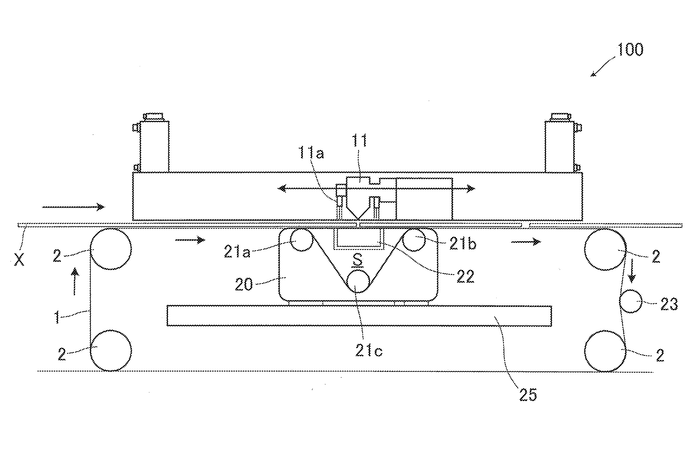
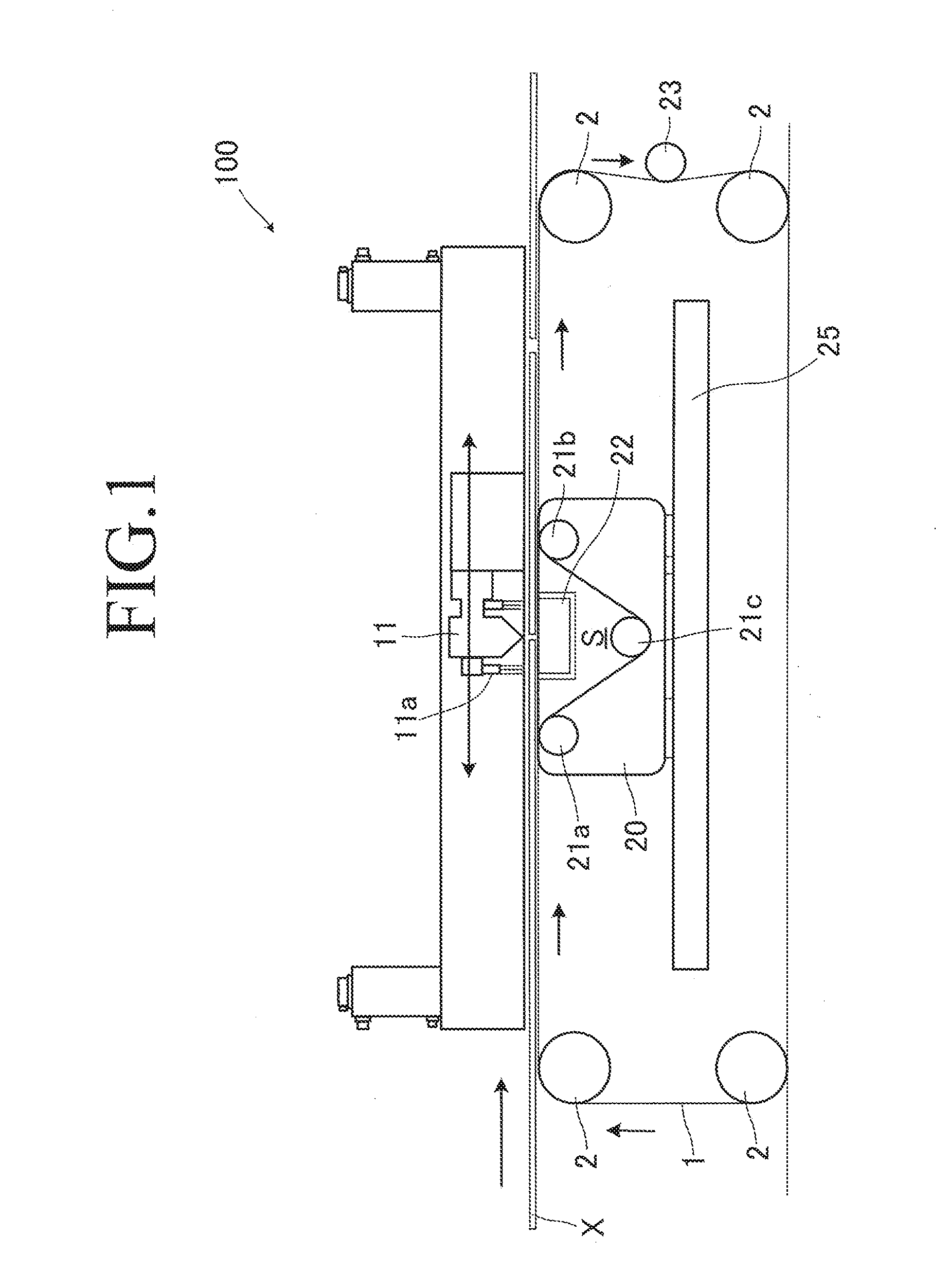
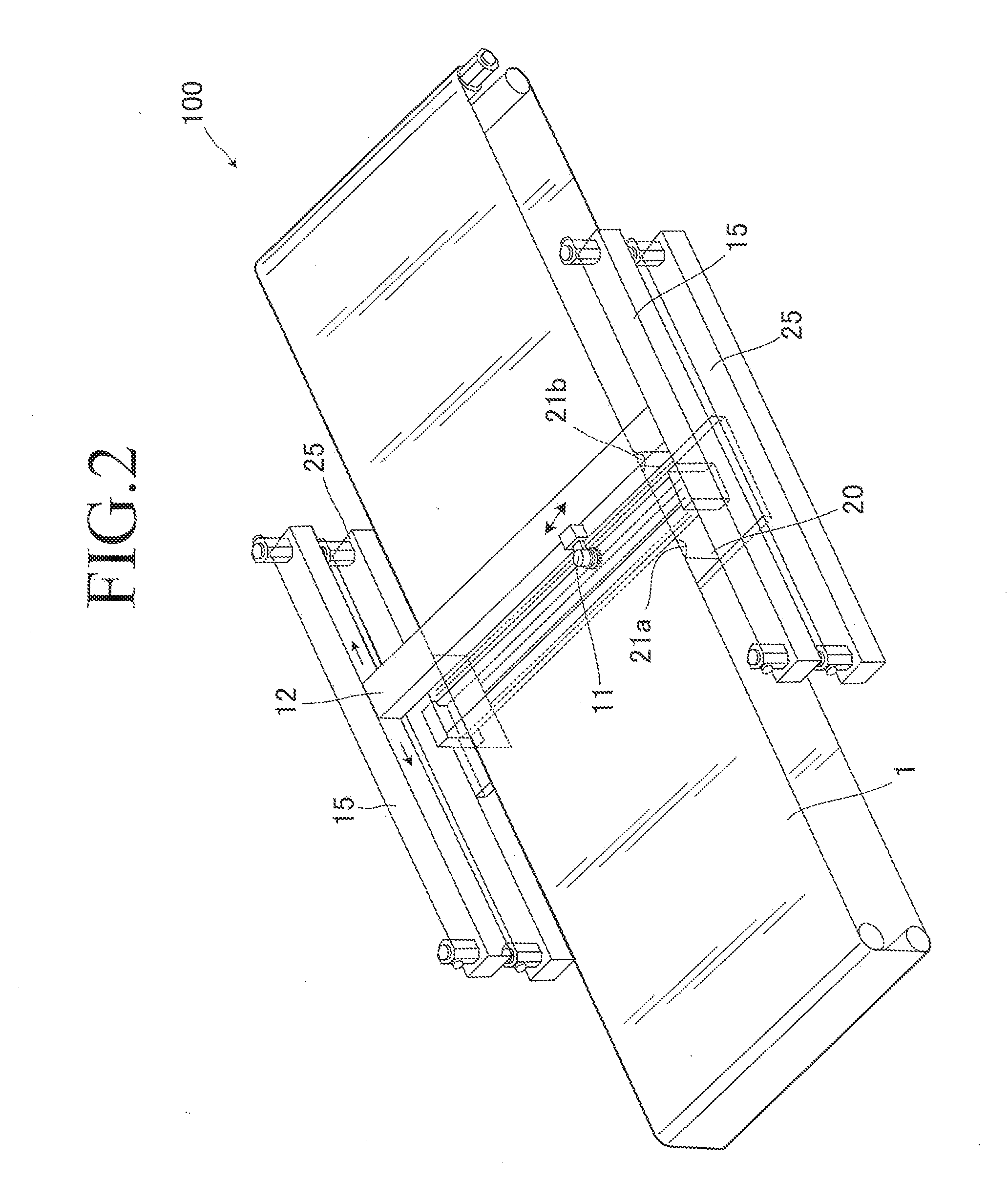
[0053]A laser blanking apparatus of the present invention is an apparatus that, while conveying a flat plate material, cuts the plate material into a blank material of a desired shape with laser light emitted from a laser nozzle.

[0054]Note here that the laser light is not limited to a particular type of laser light, but usable examples of the laser light include a solid-state laser, a liquid laser, a gas laser, a semiconductor laser, a free electron laser, a metal vapor laser, and a chemical laser.

[0055]...


PUM

PropertyMeasurementUnit
Tensionaaaaaaaaaa

Abstract

[Object] To provide a laser blanking apparatus that saves space, is easy to install, and yet is capable of laser-processing a plate material into a desired shape without causing misalignment while conveying the plate material and a processing method using the same.
[Solution] The present invention is directed to a laser blanking apparatus 100 that, while conveying a flat plate material X, cuts the plate material X into a blank material with laser light emitted from a laser nozzle 11, including: an endless conveyor 1 for feeding the plate material X; a pair of upstream and downstream support rollers 21a and 21b provided below the laser nozzle 11; and a drawing roller 21c provided below the upstream and downstream support rollers 21a and 21b, wherein the upstream and downstream support rollers 21a and 21b and the drawing roller 21c guide the endless conveyor 1.

Description

TECHNICAL FIELD[0001]The present invention relates to laser blanking apparatuses and processing methods using the same and, more particularly, to a laser blanking apparatus that saves space, is simple in structure, and yet is capable of cutting a plate material such as a steel plate into a desired shape at a desired position without causing misalignment and a processing method using the same.BACKGROUND ART[0002]In press working, generally, a flat plate material unwound from a coiled plate material is cut by a shearing apparatus into a blank material, and the blank material is pressed.[0003]Specifically, the shearing apparatus cuts the plate material into a certain shape by putting the plate material between its upper and lower blades (for example, see Patent Literature 1), and then the blank material is conveyed to a press machine pressed into a desired three-dimensional shape.[0004]Incidentally, in the case of a conventional shearing apparatus, the shape of a blank material depends...

Claims


Application Information

Patent Timeline
IPC IPC(8): B23K26/08B23K26/38
CPCB23K26/38B23K26/0838B23K26/0846
Inventor OKAZAKI, AKIRA
Owner HITACHI ZOSEN FUKUI CORP
Why Eureka
Try Eureka