Arc welding/brazing process for low-heat input copper joining

a low-heat input, copper welding technology, applied in the direction of windings, welding apparatus, manufacturing tools, etc., can solve the problem of limiting the available welding/brazing techniques that can be employed, and achieve the effect of reducing thermal damag

Inactive Publication Date: 2016-07-28
GM GLOBAL TECH OPERATIONS LLC
View PDF22 Cites 5 Cited by
  • Summary
  • Abstract
  • Description
  • Claims
  • Application Information

AI Technical Summary

Benefits of technology

[0005]The disclosed arc welding / brazing process uses a non-consumable electrode wire, which electrically communicates with a weld control in a straight polarity orientation, to strike an arc across a gap established between a leading tip end of the electrode wire and the first copper piece. The current that flows through the arc when the arc is established heats the first copper piece and thereby causes the first copper piece and the second copper piece to become joined either by an autogenous weld joint or a braze joint depending on the particulars of the process. A variety of parameters of the arc welding / brazing process can be controlled to limit the amount heat input into the copper pieces that exceeds what is needed to attain the desired joint between the copper pieces. Such control of the overall heat input is helpful in mitigating the thermal damage to heat sensitive materials that may be present in the vicinity of the joining site.

Problems solved by technology

Moreover, to further complicate the joining process, only single-side access is typically available to the protruding ends of the copper wires, which limits the available welding / brazing techniques that can be employed.

Method used


Image

  • Arc welding/brazing process for low-heat input copper joining
  • Arc welding/brazing process for low-heat input copper joining
  • Arc welding/brazing process for low-heat input copper joining

Examples


Embodiment Construction

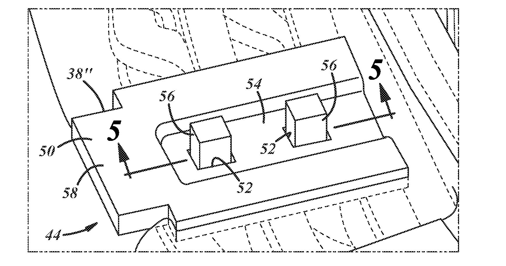
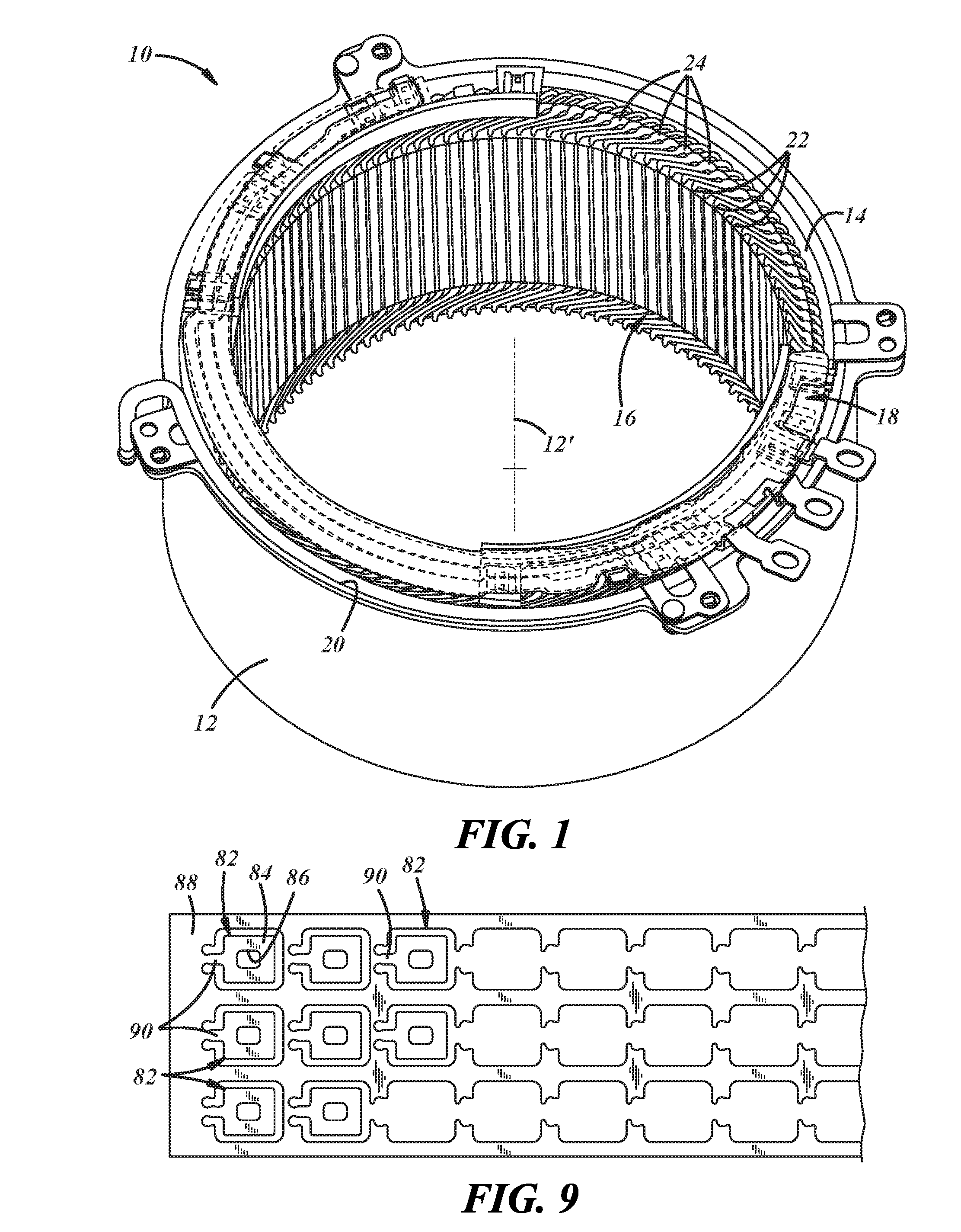
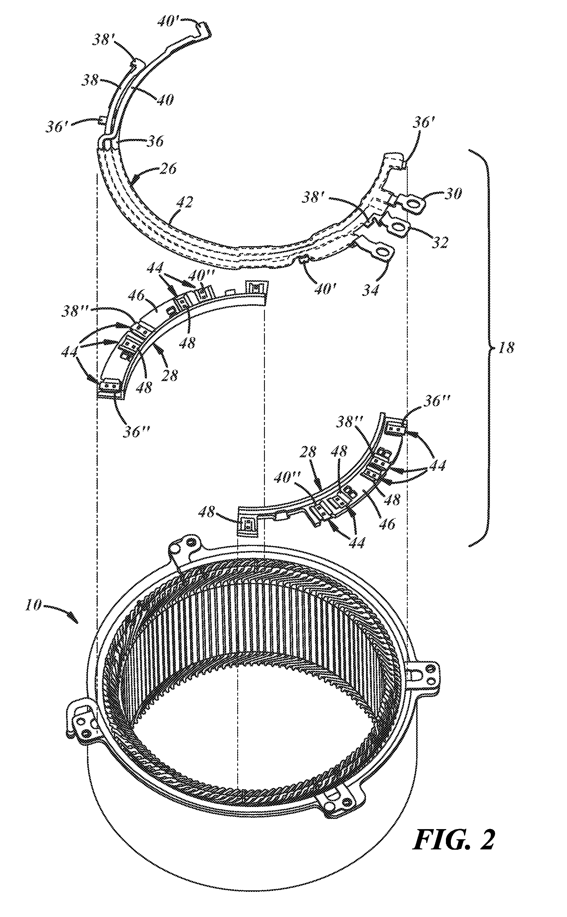
[0015]The need to join metal portions of a component without damaging or otherwise thermally degrading other portions of the component that are more sensitive to the attendant heat that accompanies the joining process is a manufacturing constraint that may arise in a variety of contexts. In particular, as demonstrated here and shown in FIGS. 1-3, a stator 10 for a 3-phase AC automobile electric motor may require a number of localized joints to be made between highly thermally- and electrically-conductive copper pieces that are in close proximity to more heat-sensitive electrically-insulating materials. Avoiding unacceptable thermal degradation to such electrically-insulating materials during the joining process helps ensure the automobile electric motor operates as efficiently as possible. Unfortunately, the preservation of electrically-insulating materials in close proximity to the copper joining locations has proven difficult to consistently achieve in the tight spatial confines o...


PUM

PropertyMeasurementUnit
diameteraaaaaaaaaa
diameteraaaaaaaaaa
standoff distanceaaaaaaaaaa

Abstract

An arc welding/brazing process is disclosed that is useful to join together a first copper piece and a second copper piece without damaging more heat-sensitive materials that may be located nearby is disclosed. The arc welding/brazing process includes using a non-consumable electrode wire, which electrically communicates with a weld control in a straight polarity orientation, to strike an arc across a gap established between a leading tip end of the electrode wire and the first copper piece. The current that flows through the arc when the arc is established heats the first copper piece such that the first copper piece becomes joined to a second copper piece. The joint between the first copper piece and the second copper piece may be an autogenous weld joint or a braze joint.

Description

[0001]This application claims the benefit of U.S. provisional patent application No. 62 / 107,045, filed on Jan. 23, 2015, the entire contents of which are hereby incorporated by reference.TECHNICAL FIELD[0002]The technical field of this disclosure relates generally to copper joining processes and, more particularly, to a controllable low-heat input copper joining process.BACKGROUND[0003]The assembly of certain types of components may require metal parts to be joined by welding or brazing without thermally damaging nearby portions of the same component that may be more sensitive to heat. For example, when assembling a stator of an electric motor, the copper wires of different phase windings distributed around the stator core typically have to be joined to a copper tab within a connection ring in order to electrically connect the phase windings to an external power source. The copper tab is usually held in a polymer body and includes a depressed well that receives protruding ends of th...

Claims


Application Information

Patent Timeline
Patent Type & Authority Applications(United States)
IPC IPC(8): H02K15/00B23K35/22B23K9/23B23K1/19B23K1/00B23K9/00
CPCH02K15/0068B23K1/0008B23K9/0008B23K2203/12B23K1/19B23K35/222B23K9/23B23K1/0016B23K9/167B23K2101/32B23K2101/36B23K2103/12H02K3/50H02K15/0081
Inventor SCHROTH, JAMES G.PERRY, THOMAS A.AGAPIOU, JOHN S.LESPERANCE, RONALD M.
Owner GM GLOBAL TECH OPERATIONS LLC
Why Eureka
Try Eureka