
Mobile terminal and method for data transmission in a radio cell thereof

a mobile terminal and radio cell technology, applied in the direction of electrical equipment, synchronisation arrangement, wireless communication, etc., can solve the problems of unprecedented wireless network challenges, limited wireless network capacity improvement, and may not meet the increasing capacity requirement, so as to improve the coverage of the whole radio cell, wide coverage, and the effect of large transmission scop

Active Publication Date: 2016-07-28
SAMSUNG ELECTRONICS CO LTD
View PDF5 Cites 23 Cited by
  • Summary
  • Abstract
  • Description
  • Claims
  • Application Information

AI Technical Summary

Benefits of technology

The present patent proposes a mobile terminal and a method for data transmission in a radio cell with improved coverage of a high frequency band cell. The method includes using an auxiliary carrier in a low frequency band to support running of a high frequency band cell. This improves the coverage of the whole radio cell and enhances reliability of radio signaling. Overall, the method improves performance of the radio cell, especially the high frequency band cell.

Problems solved by technology

Nowadays, with popularity of intelligent mobile terminals and development of wireless internet services, mobile data services tend to be booming, which brings unprecedented challenges for wireless networks.
However, since the range of carrier frequencies currently being used for wireless communication is 700 MHz-2.6 GHz, and bandwidth of available frequency spectrum resources is still very limited, new technologies such as CA, large scale MIMO, CoMP, etc. only improve peak communication rate of a single subscriber or frequency spectrum effectiveness of a certain cell to some extent, and in the given range of the frequency spectrum resources, improvements to wireless network capacity are limited, which maynot meet the increasing capacity requirement.
Especially, it is predicted that compared to what it is now, by year 2020, the wireless network capacity may grow 1000 times, and the capacity requirement maynot be met by only improving the frequency spectrum efficiency.
While with the heterogeneous network architecture being put forward, though deployment technologies of more intensive small cells are still developing and the frequencies are reused by way of increasing low power access points to improve the capacity, subjected to influences by factors such as base station site selection, device installation, backhaul network construction, etc., costs of realizing small cells are very high, and to increase the capacity, simply increasing the number of small cell sites is not enough.
So only by using the small cell technology, it is difficult to meet the increasing wireless data service requirement.
However, the frequency spectrum resources are rare and frequency spectrum resources of low frequency bands are very congested (e.g., 700 MHz-2.6 GHz currently being used in wireless communication), and there is a tendency of developing higher frequency bands.
However, the millimeter wave has weakness that it maynot evade.
Therefore, if the millimeter wave is used to cover wireless communication cells, the weakness will dramatically influence the coverage of the millimeter wave cells.
Realization of beamforming relies on estimate of radio channels, while estimate of radio channels is generally realized by using a reference signal, but during an actual communication process, during transmission of messages at an initial stage of establishing a connection between a wireless terminal and a base station, e.g., a first downlink message, the base station is unable to obtain information of radio channels, which will affect coverage of wireless signals that carry the messages, however, the messages are critical for establishing a wireless link between the terminal and the base station.
In addition, due to restriction on sizes of mobile terminals, generally, large scale MIMO may not be performed on a terminal side.
Therefore, during uplink transmission, concentration degree of beams will be smaller than that of beams during point-to-point downlink transmission, and there is an asymmetric problem existing in coverage of uplink and downlink signals.

Method used


Image

  • Mobile terminal and method for data transmission in a radio cell thereof
  • Mobile terminal and method for data transmission in a radio cell thereof
  • Mobile terminal and method for data transmission in a radio cell thereof

Examples


Embodiment Construction

[0077]To make the object, technical means and advantages of the present application clearer, detailed description will be provided in combination with attached drawings in the following.

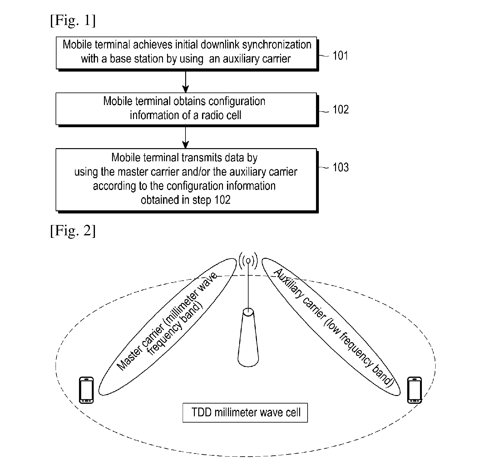
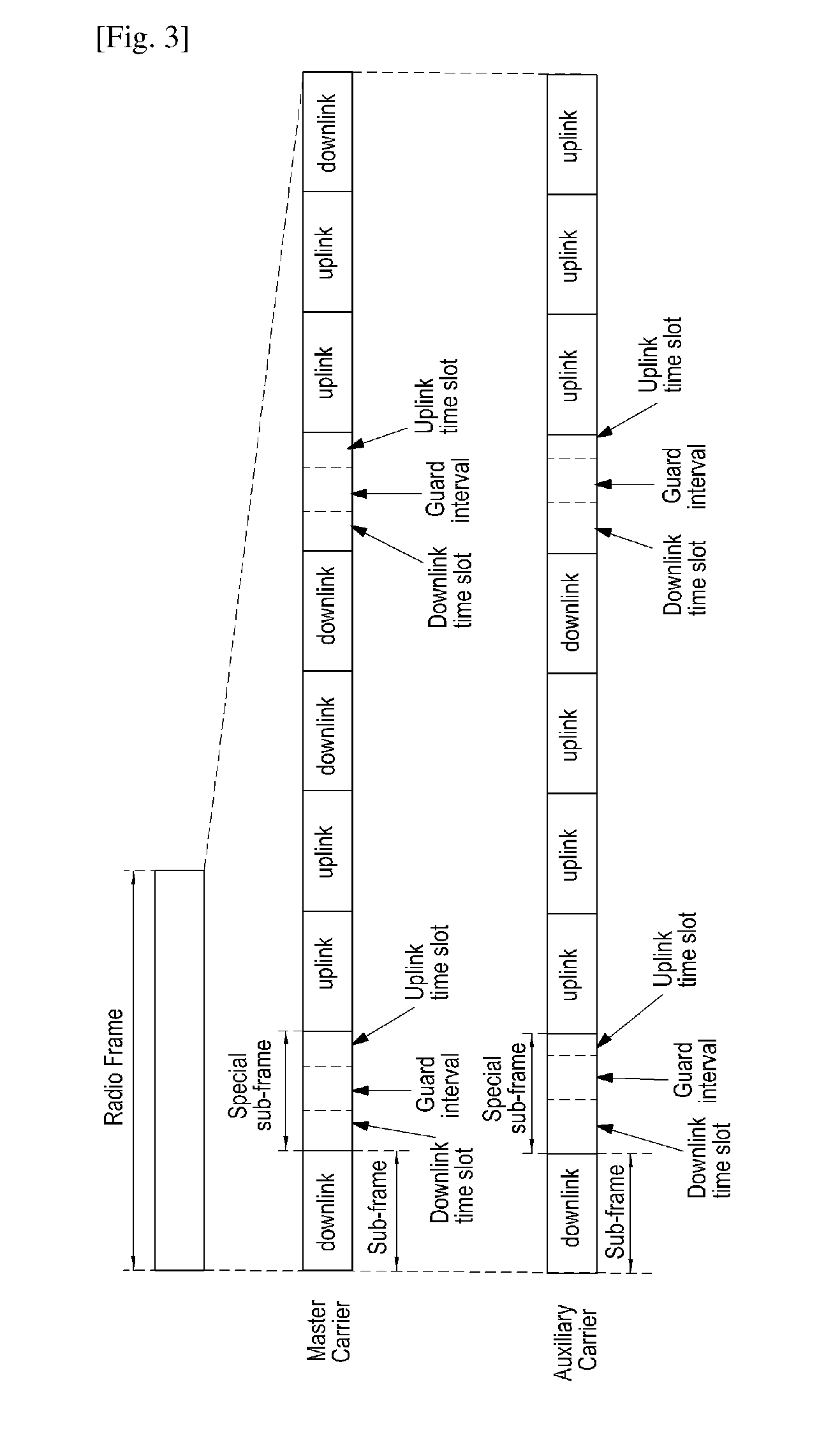
[0078]In a method for data transmission in a radio cell of a mobile terminal according to the present application, and in a method for realizing a radio cell based on low frequency auxiliary carriers and master carriers in a high frequency band, a radio cell at least supports two kinds of carriers. The first kind of carrier is master carrier, which may be one or more. A master carrier is a high frequency band carrier, used to provide downlink data service transmission. Another kind of carrier is auxiliary carrier, and an auxiliary carrier is a low frequency carrier, e.g., a carrier in 700 MHz-2.6 GHz frequency band currently being used for wireless communication. In the present application, a frequency band carrier, a frequency band difference between which and the highest frequency band of low frequ...


PUM


Abstract

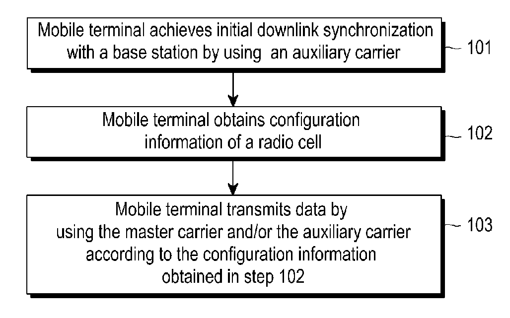
The present application discloses a method for data transmission in a radio cell of a mobile terminal. The radio cell includes an auxiliary carrier in a low frequency band and at least one master carrier in a high frequency band, the method including: the mobile terminal achieving downlink synchronization with the radio cell through the auxiliary carrier in the low frequency band, and after achieving the downlink synchronization, obtaining configuration information of the radio cell, and transmitting data by using the master carrier and / or the auxiliary carrier according to the configuration information. The present application also provides a mobile terminal. By using the present application, radio cell coverage and transmission performance may be improved.

Description

TECHNICAL FIELD[0001]The present disclosure relates to mobile communication data transmission, and particularly to a mobile terminal and a method for data transmission in a radio cell thereof.BACKGROUND ART[0002]Nowadays, with popularity of intelligent mobile terminals and development of wireless internet services, mobile data services tend to be booming, which brings unprecedented challenges for wireless networks. To meet mobile broadband requirements, currently 4G Long Time Evolution (LTE) networks adopt various technologies such as carrier aggregation (CA), large scale MIMO, Coordinated Multi-Point (CoMP), etc. to improve wireless network capacity, and to further improve frequency spectrum effectiveness, researches for small cells are being actively pushed.[0003]However, since the range of carrier frequencies currently being used for wireless communication is 700 MHz-2.6 GHz, and bandwidth of available frequency spectrum resources is still very limited, new technologies such as C...

Claims


Application Information

Patent Timeline
IPC IPC(8): H04W56/00H04W72/02
CPCH04W72/02H04W56/00
Inventor ZHANG, SHICHANGYU, BINSUN, CHENGJUN
Owner SAMSUNG ELECTRONICS CO LTD
Learn More