Holder for fastening a component to an internal combustion engine

a technology for fastening components and internal combustion engines, which is applied in the direction of machines/engines, fuel injection apparatus, and feed systems, etc., can solve the problems of increasing the angle of the component(s) to be attached, increasing the difficulty of assembly, so as to improve the controllability of the soldering process and improve the checkability of the solder result. , the effect of reducing the solder area

Active Publication Date: 2016-08-04
ROBERT BOSCH GMBH
View PDF28 Cites 3 Cited by
  • Summary
  • Abstract
  • Description
  • Claims
  • Application Information

AI Technical Summary

Benefits of technology

[0023]In addition, the solder area may be reduced, which results in better controllability of the soldering process. Furthermore, better checkability of the solder result is achieved through better access, in particular across 360 degrees, and less soldering means lower costs.
[0024]In addition, increased component rigidity at relatively large clearances between an axis, in particular a tube axis, of the component and of fastening points on the connection element is able to be obtained. The component rigidity can also be adjusted as desired by installing corresponding supplementary parts. The result is a design that is optimized with regard to cost and robustness. For example, an additional reinforcement between two adjacently disposed connection elements may be added. This results in greatly enhanced component rigidity at little extra expense.
[0025]In addition, the influence of the intrinsic stress in subsequent processes can be reduced considerably, which makes it possible to increase the quality of the subassembly.

Problems solved by technology

The mounting of the fuel rail on the internal combustion engine described in U.S. Pat. No. 7,406,946 B1 has the disadvantage that tension peaks arise because of notches, in particular at the transition between the connection element of the holder and the tubular base element of the fuel rail.
Another disadvantage is that the individual components, especially the connection element of the holder and the tubular base element of the fuel rail, must be radially held in place during the joining process in order to achieve the desired position on the joined component.
This becomes even more difficult as the enclosure angle of the component(s) to be attached becomes smaller.
Another disadvantage may result with regard to a pre-joining process.
Especially in a pre-joining process that is carried out in the form of tacking, especially by welding, for the positioning prior to a subsequent soldering process for the final connection, the welding connection frequently breaks before the final fixation, which consequently results in scrapped pieces.
In addition, tacking points may weaken the tubular base element and the attachment part(s).
These residual stresses may also be unleashed by subsequent manufacturing processes, such as a heat treatment during the soldering process, which has a considerable adverse effect on the dimensional accuracy of the finished components.
Because of the specifications, in particular the connection to the tubular base element, the space and the connection geometry, as well as the contour resulting therefrom, the typically reformed attachment parts furthermore have geometrically disadvantageous regions, such as notches, which lead to stress characteristics that feature stress peaks.
Furthermore, the typically radial connection requires a large solder surface since it is stressed with regard to pealing.
This results in poor controllability of the soldering process.
In addition, the risk of flaws in the soldering surface grows as the contact area becomes larger.
A lot of solder is required for large soldering surfaces, which is also disadvantageous from the financial standpoint.
This results in low natural frequencies and high stressing.
In one modified development, however, it is also possible that a gap is formed between the connection arm and the further connection arm in the installed state.

Method used


Image

  • Holder for fastening a component to an internal combustion engine
  • Holder for fastening a component to an internal combustion engine
  • Holder for fastening a component to an internal combustion engine

Examples


Embodiment Construction

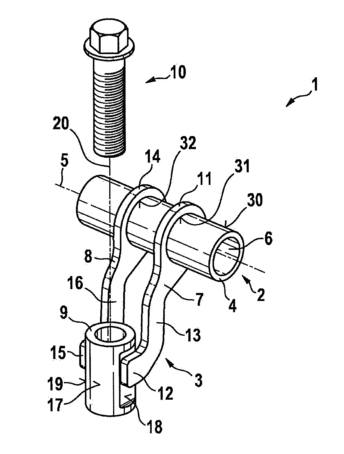
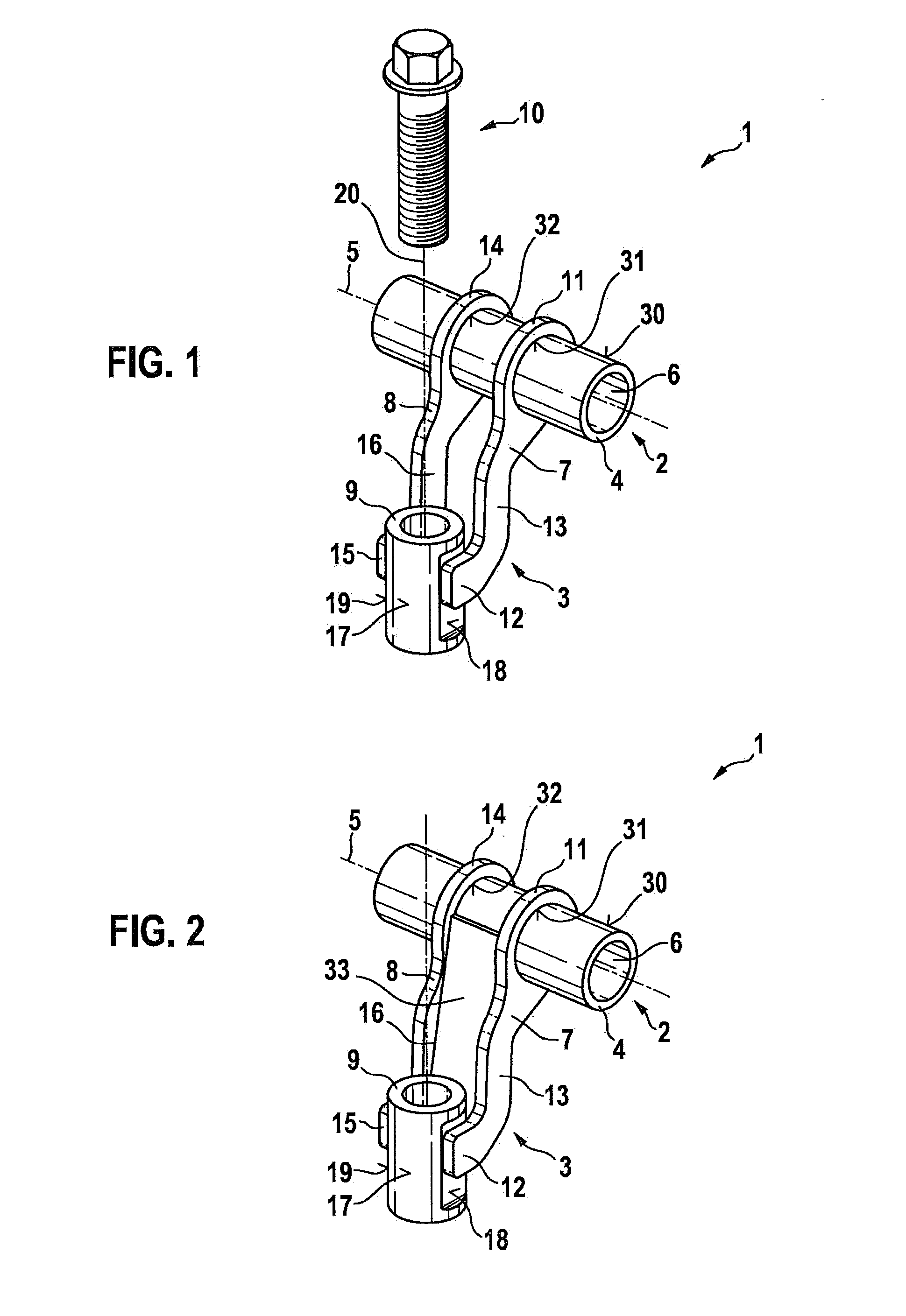
[0038]FIG. 1 shows a system 1 having a component 2 and a holder 3 in an excerpted schematic three-dimensional view according to a first exemplary embodiment. Shown here is a section of a tubular base element 4 of component 2, which extends along a longitudinal axis 5. An interior space 6 is developed within tubular base element 4, which functions as fuel space 6. During an operation fuel can be conveyed via interior space 6. For example, multiple outputs, especially cups, may be provided on tubular base element 4, via which fuel injectors are able to be supplied with fuel. Component 2 is developed as a fuel distributor in such a case. Holder 3 will then be used for fastening fuel distributor 2 to an internal combustion engine. However, holder 3 may also be used for fixating other components 2 on an internal combustion engine.

[0039]One or more further holder(s) is / are preferably provided, which may be developed similar to holder 3. This makes it possible to fasten component 2 via hol...


PUM


Abstract

A holder is used for fastening a component, in particular a fuel distributor, to an internal combustion engine. The holder has at least one connection element, which includes a locating area. In the installed state, in which the connection element rests against an outer side of the component via its locating area, the locating area of the connection element extends across an angle greater than 180 degrees in relation to a longitudinal axis of the component. Furthermore, in the installed state, in which the connection element is resting via its locating area against the outer side of the component, the locating area has the form of a cylinder jacket. In addition, a system having a component and such a holder is provided.

Description

FIELD[0001]The present invention relates to a holder for fastening a component, in particular a fuel distributor, to an internal combustion engine; it also relates to a system having a component and at least one holder. In particular, the present invention pertains to the field of fuel injection systems of internal combustion engines.BACKGROUND INFORMATION[0002]A fuel distributor rail, which is mounted on an internal combustion engine via a holder, is described in U.S. Pat. No. 7,406,946 B1. A connection element of the holder is connected via a screw to the internal combustion engine. The connection element of the holder is furthermore connected to a tubular base element of the fuel rail. It is possible that the connection element of the holder is connected to the tubular base element of the fuel rail by a solder connection.[0003]The mounting of the fuel rail on the internal combustion engine described in U.S. Pat. No. 7,406,946 B1 has the disadvantage that tension peaks arise becau...

Claims


Application Information

Patent Timeline
Patent Type & Authority Applications(United States)
IPC IPC(8): F02M61/14
CPCF02M69/465F16L3/13F02M61/14F02M63/0225F16L3/12F02M2200/857
Inventor LANG, KLAUSFROIHOFER, THOMAS
Owner ROBERT BOSCH GMBH
Why Eureka
Try Eureka