System and Method Providing Reliable Over Current Protection for Power Converter

Active Publication Date: 2016-08-04
ON BRIGHT ELECTRONICS SHANGHAI
View PDF5 Cites 81 Cited by
  • Summary
  • Abstract
  • Description
  • Claims
  • Application Information

AI Technical Summary

Benefits of technology

[0003]Certain embodiments of the present invention are directed to integrated circuits. More particularly, some embodiments of the invention provide control systems and methods for reliable over-curren

Problems solved by technology

If the OCP system is not effective, the current can reach a level at which damage to the switch is imminent due to excessive current and voltage stress at switching or thermal run-away during operation.
Consequently, the rectifier components on the transformer secondary side are subject to permanent damage due to excessive voltage and current stress in many offline flyback converters.
This limitation on maximum power can protect the power converter fro

Method used


Image

  • System and Method Providing Reliable Over Current Protection for Power Converter
  • System and Method Providing Reliable Over Current Protection for Power Converter
  • System and Method Providing Reliable Over Current Protection for Power Converter

Examples


Embodiment Construction

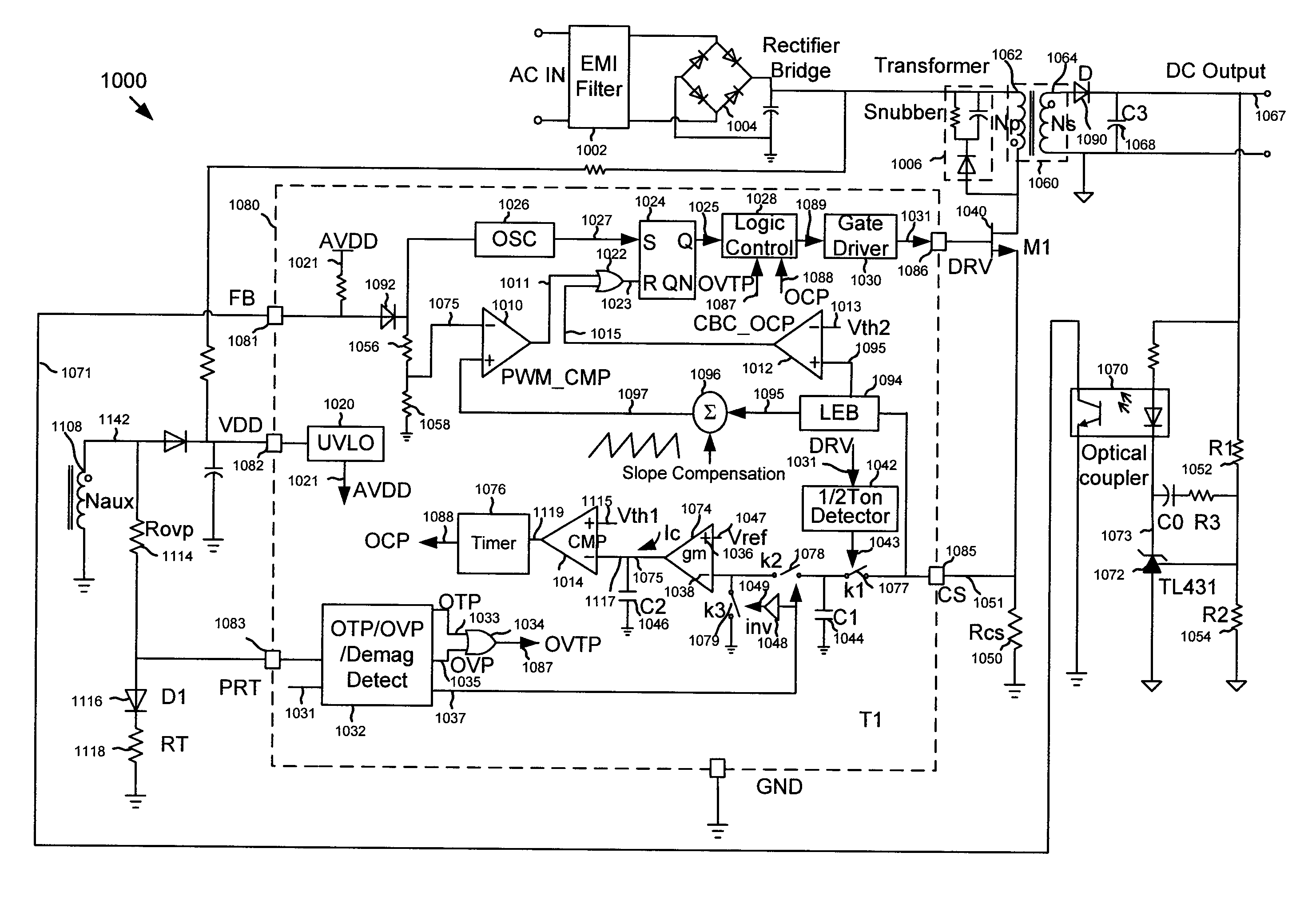
[0055]Certain embodiments of the present invention are directed to integrated circuits. More particularly, some embodiments of the invention provide control systems and methods for reliable over-current protection. Merely by way of example, some embodiments of the invention have been applied to power converters. But it would be recognized that the invention has a much broader range of applicability.

[0056]As shown by Equations 6, 7, and 8, regardless of whether a power converter works in discontinuous conduction mode (DCM) for the entire range of bulk voltage or the power converter works in continuous conduction mode (CCM) at low bulk voltage and works in DCM mode at high bulk voltage, the adjustment of the threshold for over-current protection as a function of bulk voltage depends on one or more parameters (e.g., inductance of the primary winding) of the one or more components that are outside the chip for PWM control. For example, if the adjustment of the threshold for over-current...


PUM


Abstract

System controller and method for protecting a power converter. The system controller includes a first controller terminal configured to output a drive signal to a switch to affect a first current flowing through a primary winding of a power converter. The power converter further includes a secondary winding coupled to the primary winding, and the drive signal is associated with one or more switching periods. Additionally, the system controller includes a second controller terminal configured to receive a sensing voltage from a sensing resistor. The sensing voltage represents a magnitude of the first current flowing through the primary winding of the power converter. The system controller is configured to process information associated with the sensing voltage and a reference voltage, and determine whether an average output current of the power converter is larger than a current threshold.

Description

1. CROSS-REFERENCES TO RELATED APPLICATIONS[0001]This application claims priority to Chinese Patent Application No. 201510053255.9, filed Feb. 2, 2015, incorporated by reference herein for all purposes.[0002]Additionally, U.S. patent application Ser. Nos. 13 / 749,516 and 14 / 075,303 are incorporated by reference herein for all purposes.2. BACKGROUND OF THE INVENTION[0003]Certain embodiments of the present invention are directed to integrated circuits. More particularly, some embodiments of the invention provide control systems and methods for reliable over-current protection. Merely by way of example, some embodiments of the invention have been applied to power converters. But it would be recognized that the invention has a much broader range of applicability.[0004]Power converters are widely used for consumer electronics such as portable devices. The power converters can convert electric power from one form to another form. As an example, the electric power is transformed from altern...

Claims


Application Information

Patent Timeline
IPC IPC(8): H02H7/125H02M3/335
CPCH02M3/33507H02H7/125H02H7/1257H02M1/32H02H7/12H02H9/025H02M3/33523H02M1/0009H02M1/08H02M1/44
Inventor YANG, DONGZEHUANG, XIAOMINKANG, XIAOZHILIN, YUANLYU, HUAWEIFANG, LIEYI
Owner ON BRIGHT ELECTRONICS SHANGHAI
Why Eureka
Try Eureka