

Control method for electrical converter with lc filter
- Summary
- Abstract
- Description
- Claims
- Application Information
AI Technical Summary
Benefits of technology
Problems solved by technology
Method used
Image

Examples
Embodiment Construction
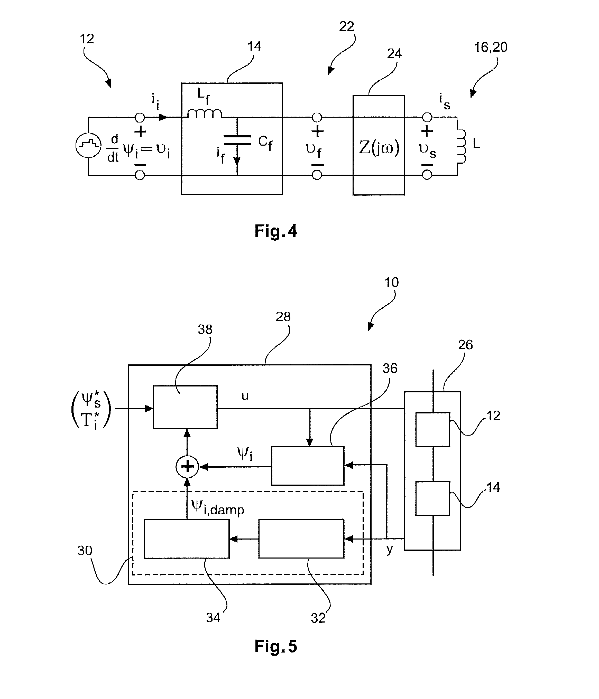
[0009]It is an object of the invention to provide an electrical converter with low power losses. It may be a further object of the invention to provide an electrical converter, which is adapted to effectively dampen oscillations caused by an LC filter.
[0010]These objects are achieved by the subject-matter of the independent claims. Further exemplary embodiments are evident from the dependent claims and the following description.
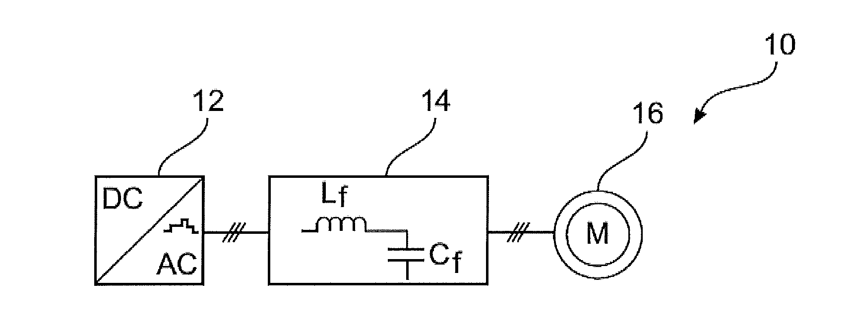
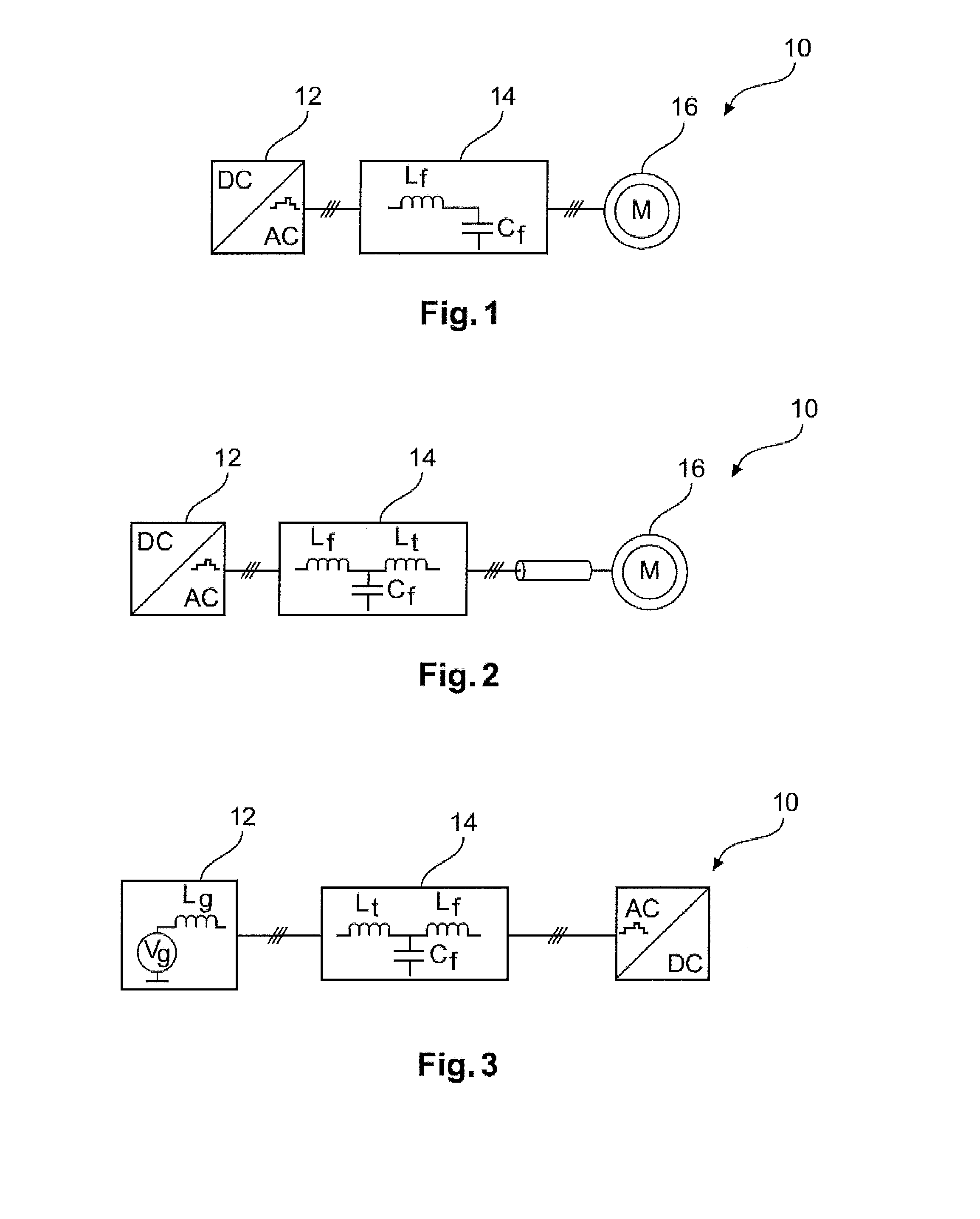
[0011]An aspect of the invention relates to a method for controlling an electrical converter interconnected via a filter with an electrical load or electrical power source. An electrical converter may be an active rectifier or inverter for transforming a DC current into an AC current and vice versa, respectively. In general, the converter may be an N-level converter, i.e. a converter having an N-level output voltage at the AC side. An electrical converter may comprise semiconductor switches that are controlled by a controller for controlling the currents flow...
PUM
 Abstract
Description
Claims
Application Information