
Digital multi-dimensional image photon platform system and methods of use

a digital multi-dimensional image and platform technology, applied in the field of image transformation and processing, can solve the problems of jumping images, fuzzy features, out of focus, etc., and achieve the effects of avoiding headaches and nausea, avoiding overlapping images, and avoiding overlapping images

Active Publication Date: 2016-08-04
NIMS JERRY +2
View PDF3 Cites 14 Cited by
  • Summary
  • Abstract
  • Description
  • Claims
  • Application Information

AI Technical Summary

Benefits of technology

The digital multi-dimensional image platform system and methods of use control the position and path of light from the original object to the human visual system. By using new hardware and software with parameters of barrier screens, lenticular, and / or waveguide, the system produces high-quality multi-dimensional images without fuzziness, doubling, or irritating distortion. The system also overcomes problems in creating the image and puts together a systematic approach to the production of the final image. Additionally, the system simplifies the development of a high-quality master digital multi-dimensional image, reducing manufacturing errors, cross talk, and distortion.

Problems solved by technology

However, viewing of the resulting digital multidimensional images in the above listed methods can present problems due to alignment of the image to the barrier screens or lens arrays.
Misalignment results in jumping images, out of focus, or fuzzy features when viewing the digital multidimensional images.
The viewing of these images can lead to headaches and nausea.
One disadvantage of this approach is that lenticular image design is limited in that it relies on a lenticular “artist” to compose by visual trial and error.
However, this traditional process accounts for only a few of the possible parameters.
Using manual and artistic calibrations limits accuracy and reduces the lenticular image three dimensional and / or motion effect.
Moreover, another disadvantage of this approach is that double images occur and are usually caused by an exaggeration of the three dimensional effect from angles of view or an insufficient number of frames.
Poor composition can lead to doubling, small jumps, a fuzzy image, or where foreground and background are fuzzy or shaded, especially on objects in relief or in depth.
Still another disadvantage of this approach is that ghosting occurs due to poor treatment of the source images, and also due to transitions where demand for an effect goes beyond the limits and technical possibilities of the system.
Here the interphase step was performed by the computer; however, errors from the lenticular material and manufacturing processes were not compensated for during the interphase step.

Method used


Image

  • Digital multi-dimensional image photon platform system and methods of use
  • Digital multi-dimensional image photon platform system and methods of use
  • Digital multi-dimensional image photon platform system and methods of use

Examples


Embodiment Construction

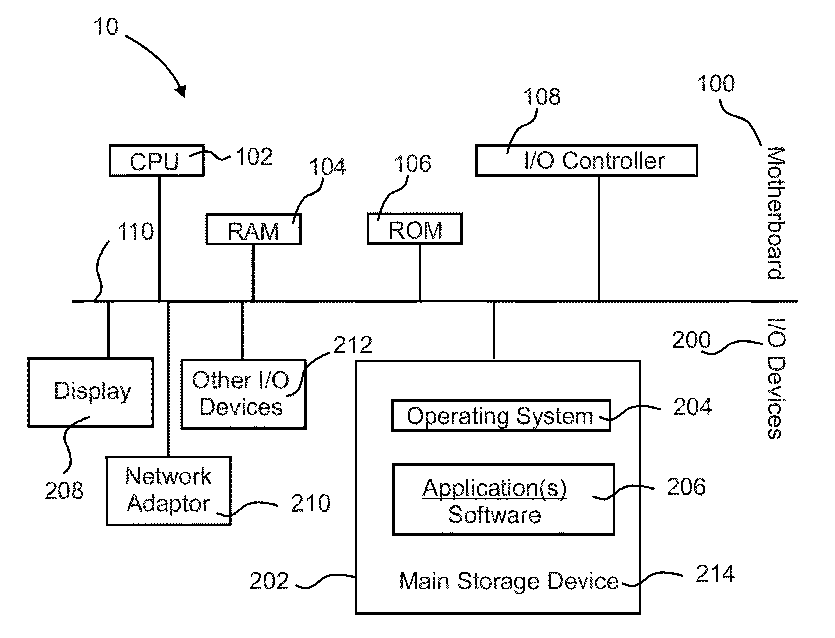
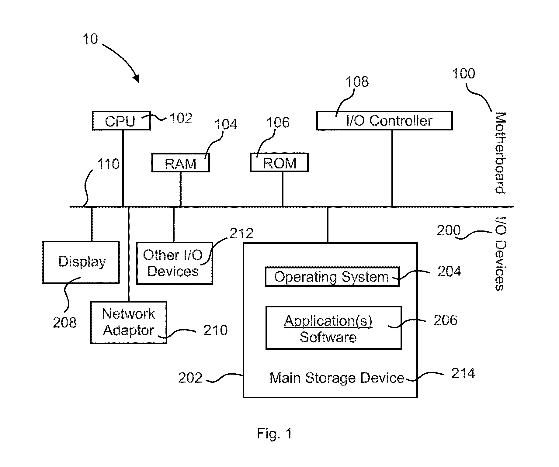
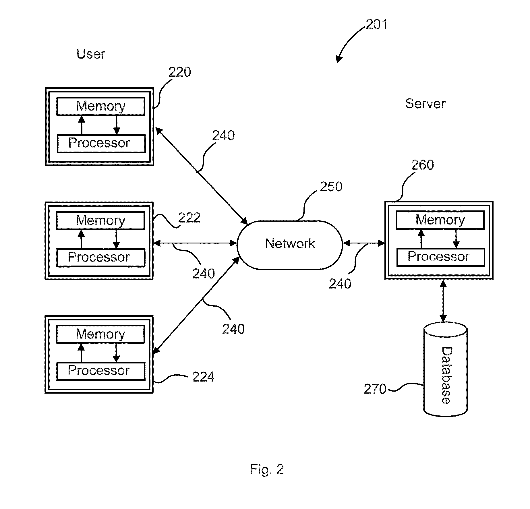
[0062]In describing the exemplary embodiments of the present disclosure, as illustrated in FIGS. 1-12, specific terminology is employed for the sake of clarity. The present disclosure, however, is not intended to be limited to the specific terminology so selected, and it is to be understood that each specific element includes all technical equivalents that operate in a similar manner to accomplish similar functions. The claimed invention may, however, be embodied in many different forms and should not be construed to be limited to the embodiments set forth herein. The examples set forth herein are non-limiting examples, and are merely examples among other possible examples.

[0063]In order to understand the present disclosure certain variables need to be defined. The object field is the entire image being composed. The “key subject point” is defined as the point where the scene converges, i.e., the point in the depth of field that always remains in focus and has no parallax differenti...


PUM


Abstract

A systematic approach to producing multi-dimensional photon images on a computer platform having applications to input image(s) from various sources, and applications to coordinate and adjust numerous variables which determine the quality of the image, such as the size of the imported images, the output image size, the resolving power of the viewing screen and the width of the resolving elements, the dots per inch of the output device (or pixels per inch), the desired nearest object, the desired furthest object and the determination of the central or the “key subject”, rules of interphasing, the number of frames or layers, the minimum parallax, and the maximum parallax, and, thus, provide a digital multi-dimensional image without jumping images or fuzzy features or other visual distortions by creating high quality output images both in the form of a printed hardcopy or as a viewed image on an appropriate viewing device.

Description

TECHNICAL FIELD[0001]The disclosure relates generally to image transformation and, more specifically, to image transformation and processing to produce consistently high quality three dimensional and other multi-dimensional images.BACKGROUND[0002]Traditional analog three dimensional images up to the age of the computer were produced using multi-lens cameras. The resulting negatives were printed on photo-emulsions. The result was either viewed and saved or scanned and digitized for printing on a lenticular screen. These images were produced by printing separate frames of the same image behind each lens. The individual frames were offset by an operator independently adjusting the depths of field relative to a central object in a central frame.Analog Photography Techniques[0003]Analog photography techniques for taking and methods of composing stereoscopic pictures employing a lenticular lens and controlling depth of field are set forth in U.S. Pat. No. 3,960,563 entitled Methods and Ap...

Claims


Application Information

Patent Timeline
Patent Type & Authority Applications(United States)
IPC IPC(8): H04N13/00H04N13/02H04N13/04B41M3/06
CPCH04N13/0409H04N13/0203H04N13/0033H04N13/0018B41M3/06H04N13/026B33Y40/00H04N2013/0081H04N13/0059H04N13/0221B33Y50/02H04N13/221H04N13/122H04N13/144H04N13/194H04N13/204H04N13/261H04N13/31
Inventor NIMS, JERRYKARSZES, WILLIAM M.POL, SAMUEL
Owner NIMS JERRY
Learn More