
Photoacoustic tracking and registration in interventional ultrasound

a technology of ultrasound and ultrasound tracking, applied in the field of ultrasound systems and methods, can solve the problems of not all clinical ultrasound systems provide access to the speed of sound for beamforming, and become limitations of real-time imaging,

Active Publication Date: 2016-08-11
THE JOHN HOPKINS UNIV SCHOOL OF MEDICINE
View PDF4 Cites 29 Cited by
  • Summary
  • Abstract
  • Description
  • Claims
  • Application Information

AI Technical Summary

Benefits of technology

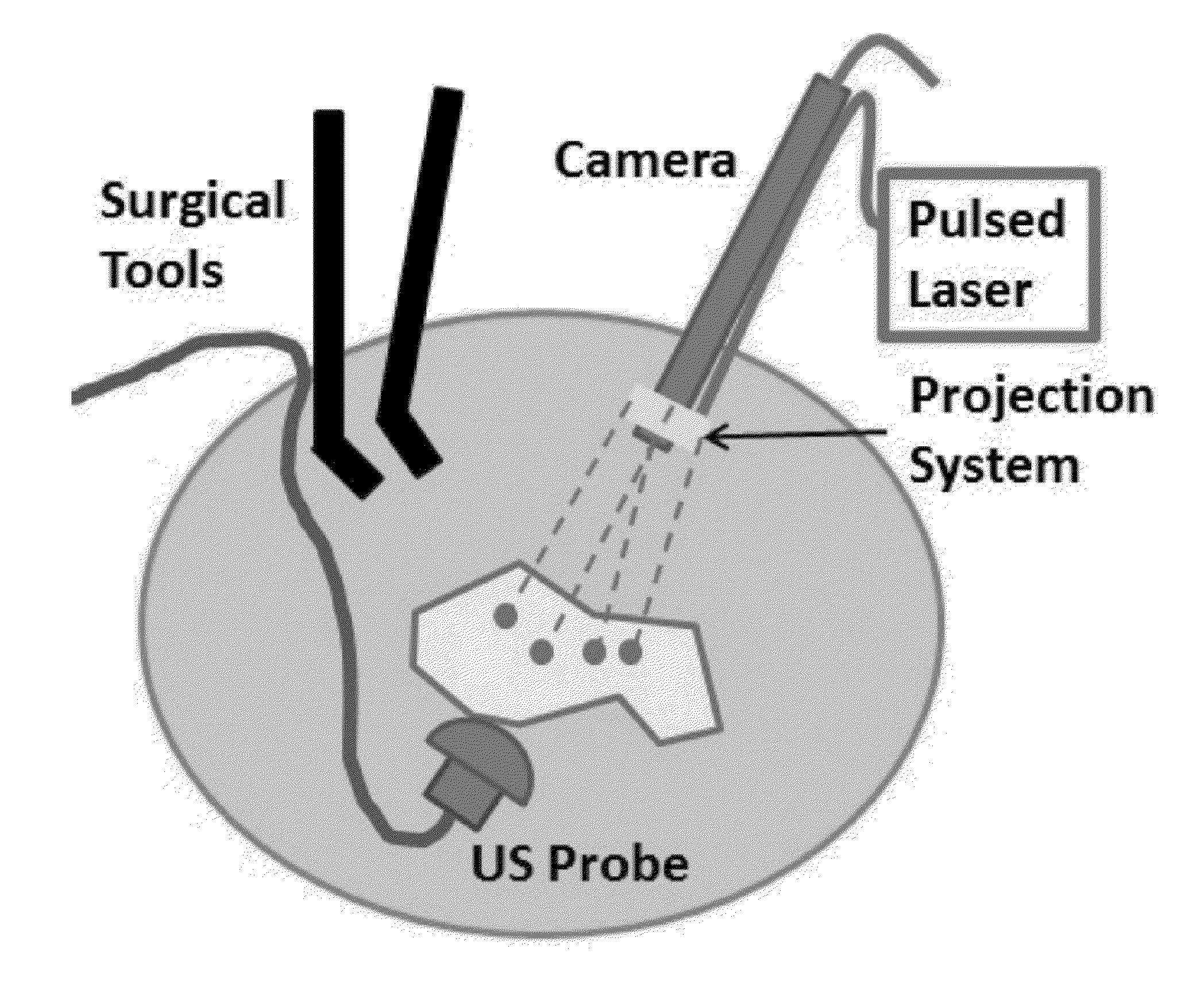
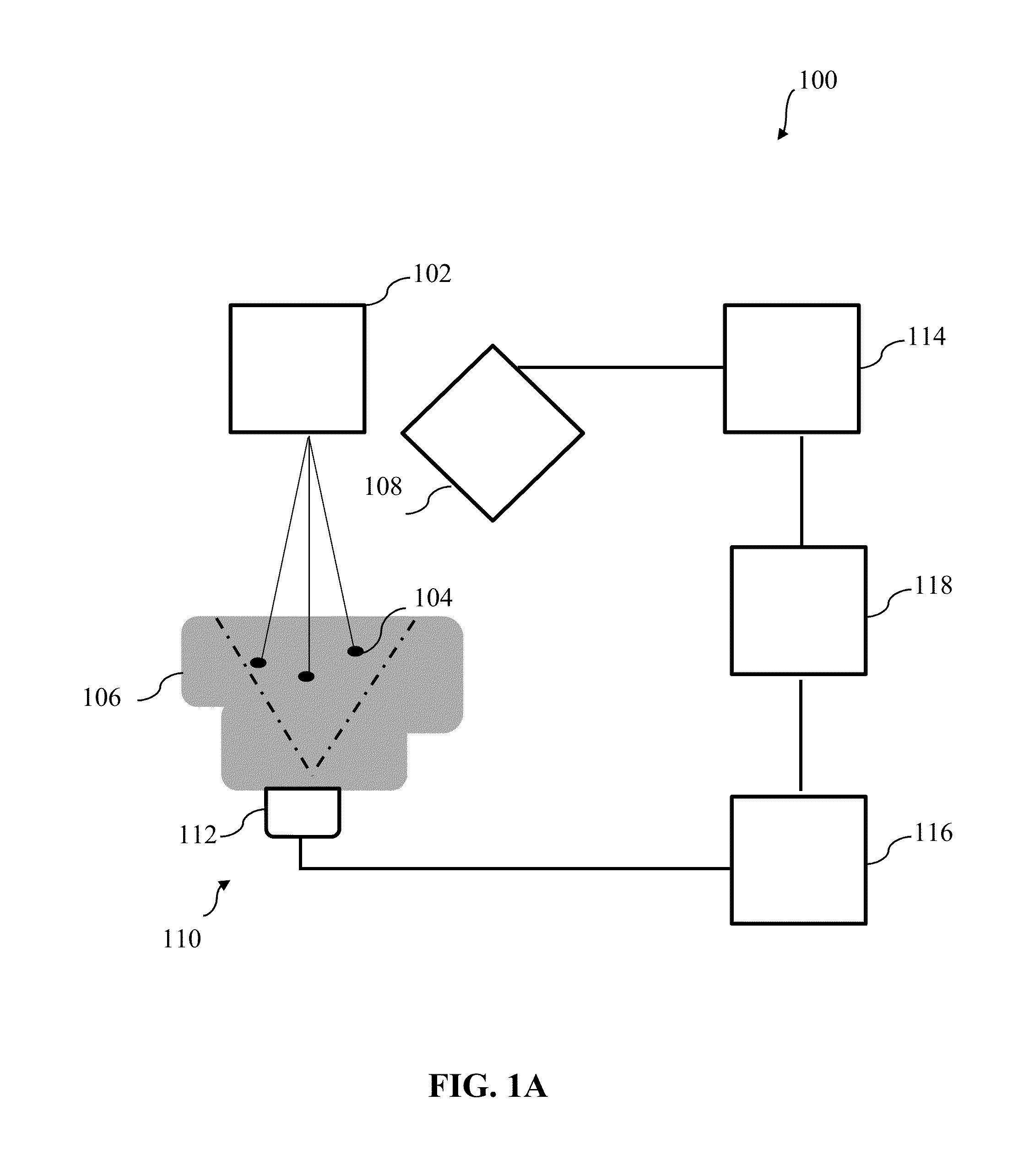
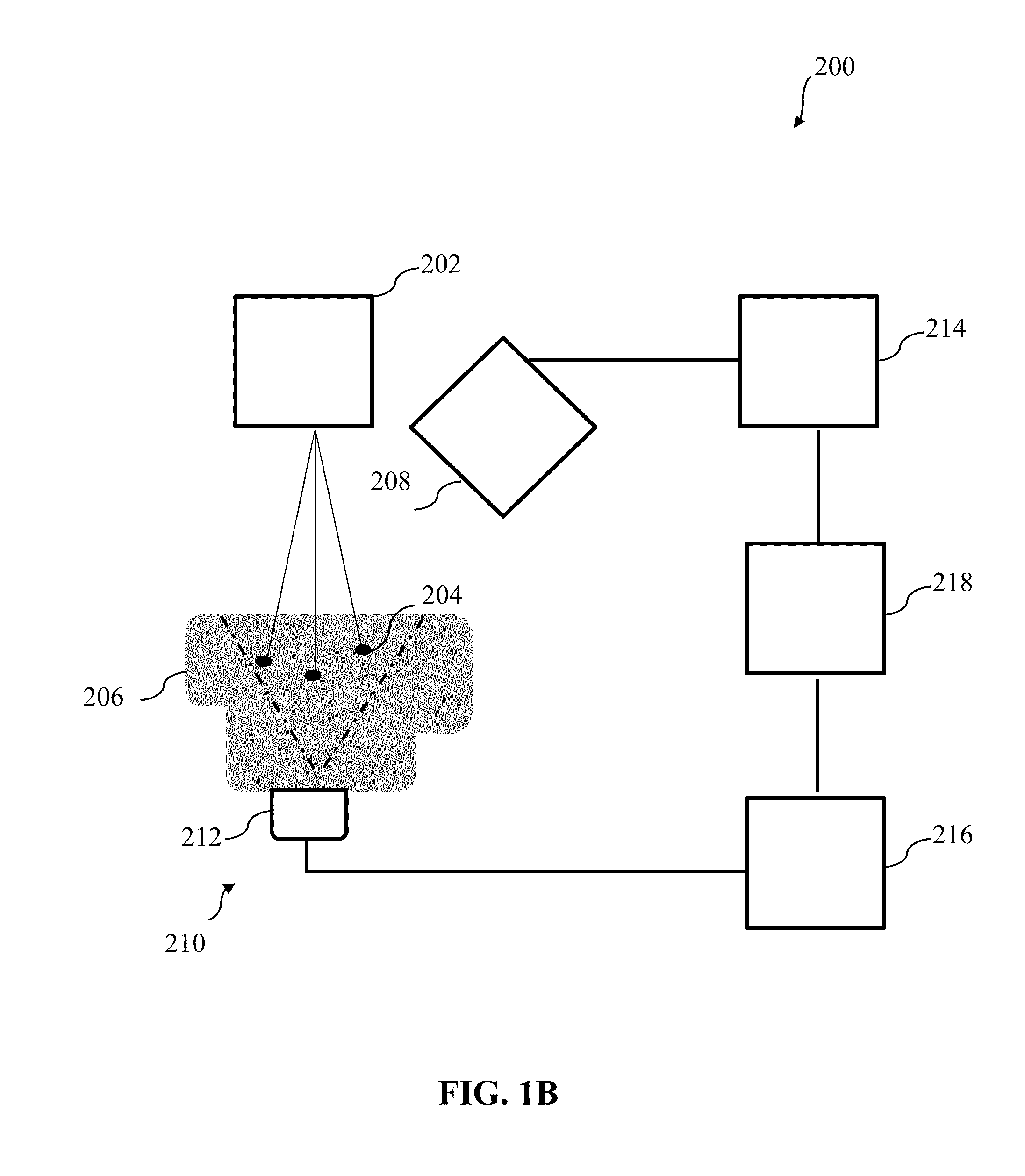
The invention is an ultrasound imaging system that can track and image a body of interest in real-time using a fiducial-marker system. The system includes an ultrasound transmitter that provides a localized ultrasound pulse at a specific spot on the body, an optical imaging system that captures an optical image of the area, and an optical image processing system that analyzes the optical image to determine the location of the ultrasound marker. The system also includes an ultrasound imaging system that uses synthetic aperture imaging to create a high-quality image. The technical effect of this invention is that it allows for more accurate and precise ultrasound imaging in real-time using a combination of ultrasound and optical markers.

Problems solved by technology

These systems are generally expensive and extensive systems take time to transfer data from the ultrasound machine, so it becomes a limitation of real-time imaging.
This fact can be an obstacle of smooth transaction for clinical application, and there is a strong demand to develop a beamforming algorithm utilizing post-beamformed radio frequency (RF) data. T. Harrison at al. has focused the same issue and their solution was to change the speed of sound value inside the clinical ultrasound system.
A limitation of the approach is that not all clinical ultrasound systems provide accessibility to the speed of sound for beamforming.

Method used


Image

  • Photoacoustic tracking and registration in interventional ultrasound
  • Photoacoustic tracking and registration in interventional ultrasound
  • Photoacoustic tracking and registration in interventional ultrasound

Examples


example 1

Direct Ultrasound to Video Registration using Photoacoustic Markers from a Single Image Pose

[0090]Modern surgical procedures including open, laparoscopic, and robotic surgeries are often aided by interventional guidance systems. [1] There is a need for these systems as surgical environments are constantly changing and tumors may only be visible under medical imaging guidance, or move in and out of the camera's field of view. Interventional guidance systems provide a fusion of video and other imaging modalities, such as interoperative ultrasound (US), to alleviate some of these concerns. This video and medical imaging fusion can support surgeons in finding and tracking tumors or other objects of interest. A registration process between surgical tools and devices, such as stereoscopic endoscopes and US transducers, is necessary to enable these guidance systems.

[0091]This example focuses on the registration between stereoscopic video and US imaging. Many surgeries require real-time US ...

references — example 1

REFERENCES—EXAMPLE 1

[0120][1] Y. Wang, S. Butner, and A. Darzi, “The developing market for medical robotics,” Proc. IEEE 94(9), 17631771 (2006).

[0121][2] R. Taylor et al., Computer Integrated Surgery, MIT Press, Cambridge, Massachusetts (1996).

[0122][3] P. J. Stolka et al., “A 3D-elastography-guided system for laparoscopic partial nephrectomies,” Proc. SPIE 7625, 762511 (2010).

[0123][4] C. L. Cheung et al., “Fused video and ultrasound images for minimally invasive partial nephrectomy: a phantom study,” Med. Image. Comput. Comput. Assist. Interv. 13(3), 408-415 (2010).

[0124][5] N. Navab, M. Mitschke, and O. Schutz, “Camera-augmented mobile C-arm (CAMC) application: 3D reconstruction using low cost mobile C-arm,” Med. Image. Comput. Comput. Assist. Interv. 1679, 688-697 (1999).

[0125][6] A. Wiles, D. Thompson, and D. Frantz, “Accuracy assessment and interpretation for optical tracking systems,” Proc. SPIE 5367, 421-432 (2004).

[0126][7] E. Boctor et al., “A novel closed form solution fo...

example 2

Photoacoustic Reconstruction Using Beamformed RF Data: A Synthetic Aperture Imaging Approach

[0143]Photoacoustic (PA) imaging is becoming an important tool for various clinical and pre-clinical applications. Acquiring pre-beamformed channel ultrasound data is essential to reconstruct PA images [1-2]. Accessing these pre-beamformed channel data requires custom hardware to allow parallel beam-forming, and is available for only few research ultrasound platforms or dedicated channel data extension device such as DAQ system. These systems are generally expensive and extensive systems takes time to transfer data from ultrasound machine, so it becomes a limitation of real-time imaging. This fact can be an obstacle of smooth transaction for clinical application, and there is a strong demand to develop a beamforming algorithm utilizing post-beamformed radio frequency (RF) data. T. Harrison at al. has focused the same issue and there solution was change the speed of sound number inside of clin...


PUM


Abstract

According to some embodiments of the invention, an ultrasound imaging system having real-time tracking and image registration includes a fiducial-marker system comprising an ultrasound transmitter structured to provide a localized ultrasound pulse at an optically observable localized spot on a body of interest. The system further includes an optical imaging system, a two-dimensional ultrasound imaging system, an optical image processing system, and an ultrasound image processing system The ultrasound imaging system further includes a registration system configured to communicate with the optical image processing system and the ultrasound image processing system to receive information, the registration system being further configured to determine a coordinate transformation that registers the optical image with the two-dimensional ultrasound image based at least partially on information concerning the spatial locations determined for the combined ultrasound and optical fiducial marker observed in the optical image and in the two-dimensional ultrasound image.

Description

[0001]This application claims priority to U.S. Provisional Application No. 62 / 113,918 filed Feb. 9, 2015, the entire content of which is hereby incorporated by reference.[0002]This invention was made with Government support of Grant No. EB015638, awarded by the National Institute of Biomedical Imaging and Bioengineering—National Institutes of Health, and Grant No. IIS-1162095, awarded by the National Science Foundation. The U.S. Government has certain rights in this invention.BACKGROUND[0003]1. Technical Field[0004]The field of the currently claimed embodiments of this invention relates to ultrasound systems and methods, and more particularly to ultrasound imaging systems and methods having real-time tracking and image registration.[0005]2. Discussion of Related Art[0006]Photoacoustic (PA) imaging is becoming an important tool for various clinical and pre-clinical applications. Acquiring pre-beamformed channel ultrasound data is essential to reconstruct PA images. Accessing these pr...

Claims


Application Information

Patent Timeline
Patent Type & Authority Applications(United States)
IPC IPC(8): A61B8/00A61B8/08A61B5/00
CPCA61B8/4416A61B2090/3995A61B8/5207A61B5/0095A61B8/0841A61B8/12A61B8/15A61B8/58G01S15/899A61B2090/378A61B2090/3925A61B2090/365A61B2090/3937A61B2034/2055A61B2034/2051A61B90/36A61B5/0059
Inventor BOCTOR, EMAD M.CHENG, ALEXISGUO, XIAOYUZHANG, HAICHONG K.TAYLOR, RUSSELL H.
Owner THE JOHN HOPKINS UNIV SCHOOL OF MEDICINE
Learn More