
Process and apparatus for treating sludge

a technology of sludge and processing equipment, which is applied in the direction of quarries, separation processes, and waste water treatment, etc., can solve the problems of high energy requirements, high cost, and inability to meet the requirements of sludge treatment, so as to reduce the volume of air and reduce the energy requirements

Active Publication Date: 2016-08-11
ALI JAK HLDG
View PDF8 Cites 16 Cited by
  • Summary
  • Abstract
  • Description
  • Claims
  • Application Information

AI Technical Summary

Benefits of technology

The patent describes a device for heating and evaporating sludge. The device has a conveyor with flights that form accumulations of sludge, which increases the surface area of the sludge and causes it to heat and evaporate quickly. The device also has an inlet valve to regulate the flow of sludge into the housing. This valve helps maintain a vacuum in the housing, which causes the sludge to move into the housing without losing the vacuum. The technical effects of this device include faster heating and evaporation of sludge, better contact between the sludge and heat exchanger surfaces, and reduced energy consumption.

Problems solved by technology

Drill mud is often considered contaminated waste and must be processed prior to being re-integrated with the environment.
Ordinary methods of separation, such as cyclonic separation, filtration, membranes or screens, are generally not suited for processing of drill mud to remove water.
These methods can be expensive due to the cost of constructing the pond, maintaining it during its lifetime and then reinstating the land to its original condition after the useful life of the pond.
Ponds, in particular, face a further issue, whereby evaporation of liquid from the pond can increase the concentration of chemicals in the pond.
Such chemical concentration levels can have an adverse impact on the surrounding environment.

Method used


Image

  • Process and apparatus for treating sludge
  • Process and apparatus for treating sludge
  • Process and apparatus for treating sludge

Examples


example

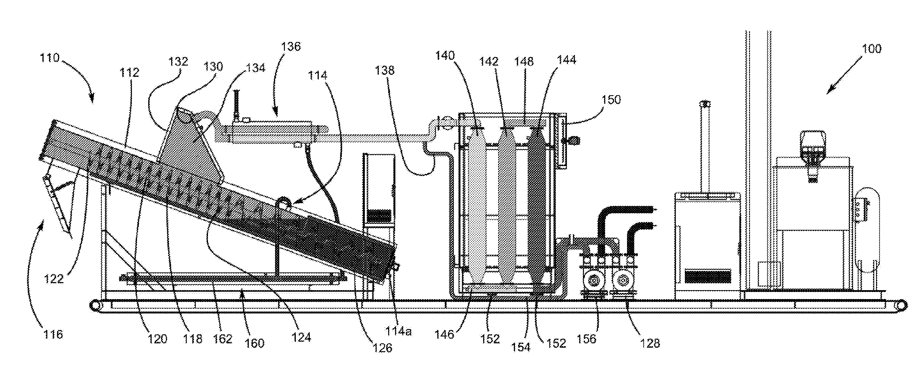
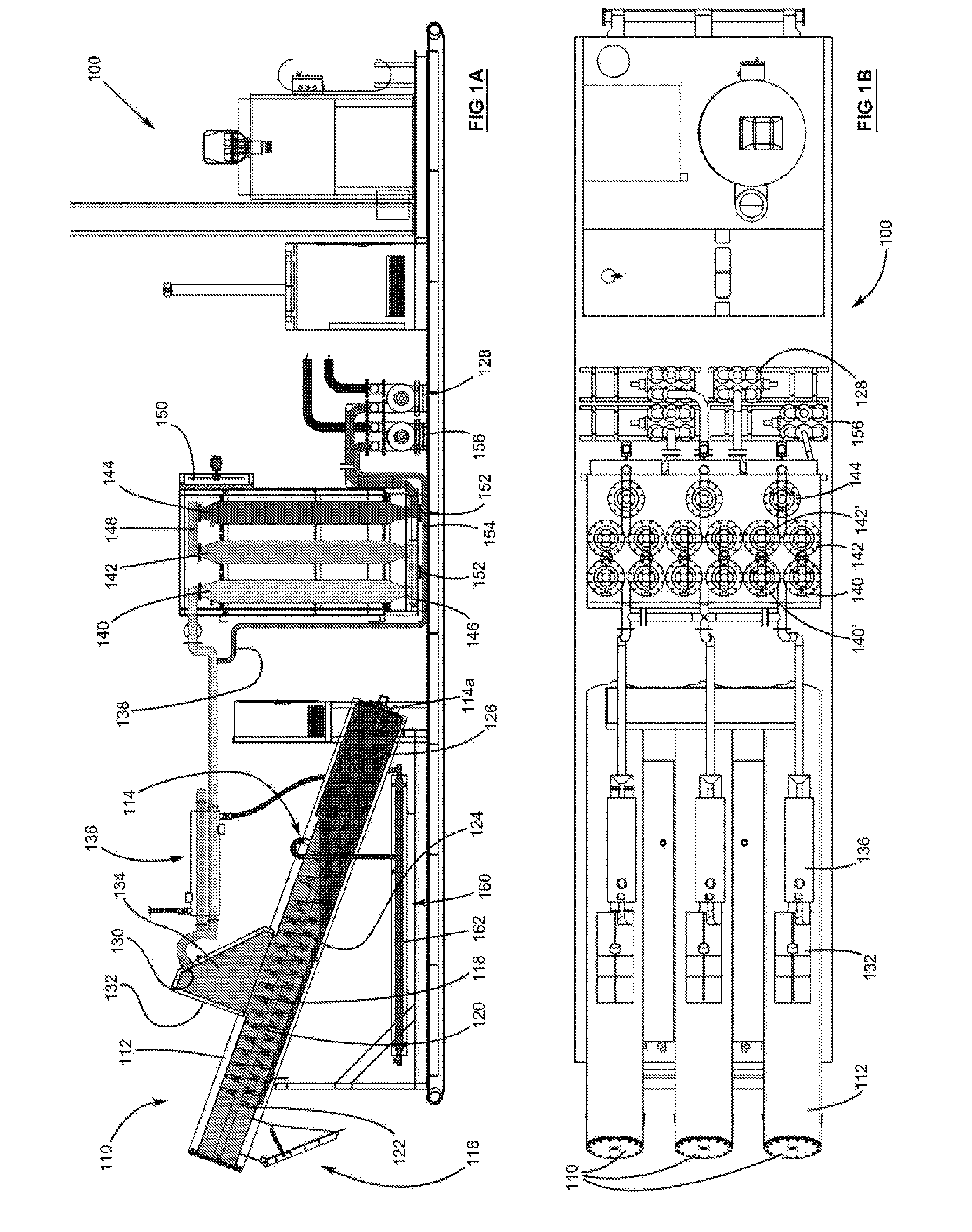
[0159]A treatment unit transported to, and setup at, a mine site. The treatment unit included three inclined drill mud treatment apparatuses supported on a single skid and powered by a diesel generator.

[0160]Drill mud was extracted from a drill mud pit and transferred to a tank located in proximity to the treatment unit. The treatment unit was connected by pipe to the tank such that drill mud from the tank flowed into the individual apparatuses of the treatment unit. The general properties of the drill mud are provided in Table 2.

TABLE 2PROPERTIES OF EXEMPLARY PRE-TREATED DRILL MUDPropertyUnitValue RangeConductivityus / cm25,000-35,000Total Dissolved Solidsmg / L20,000-30,000pHpH6-8Sodium Adsorption Ratioratio25-35Total Suspended Solidmg / L100-200Total Petroleum Hydrocarbonsmg / L5-6

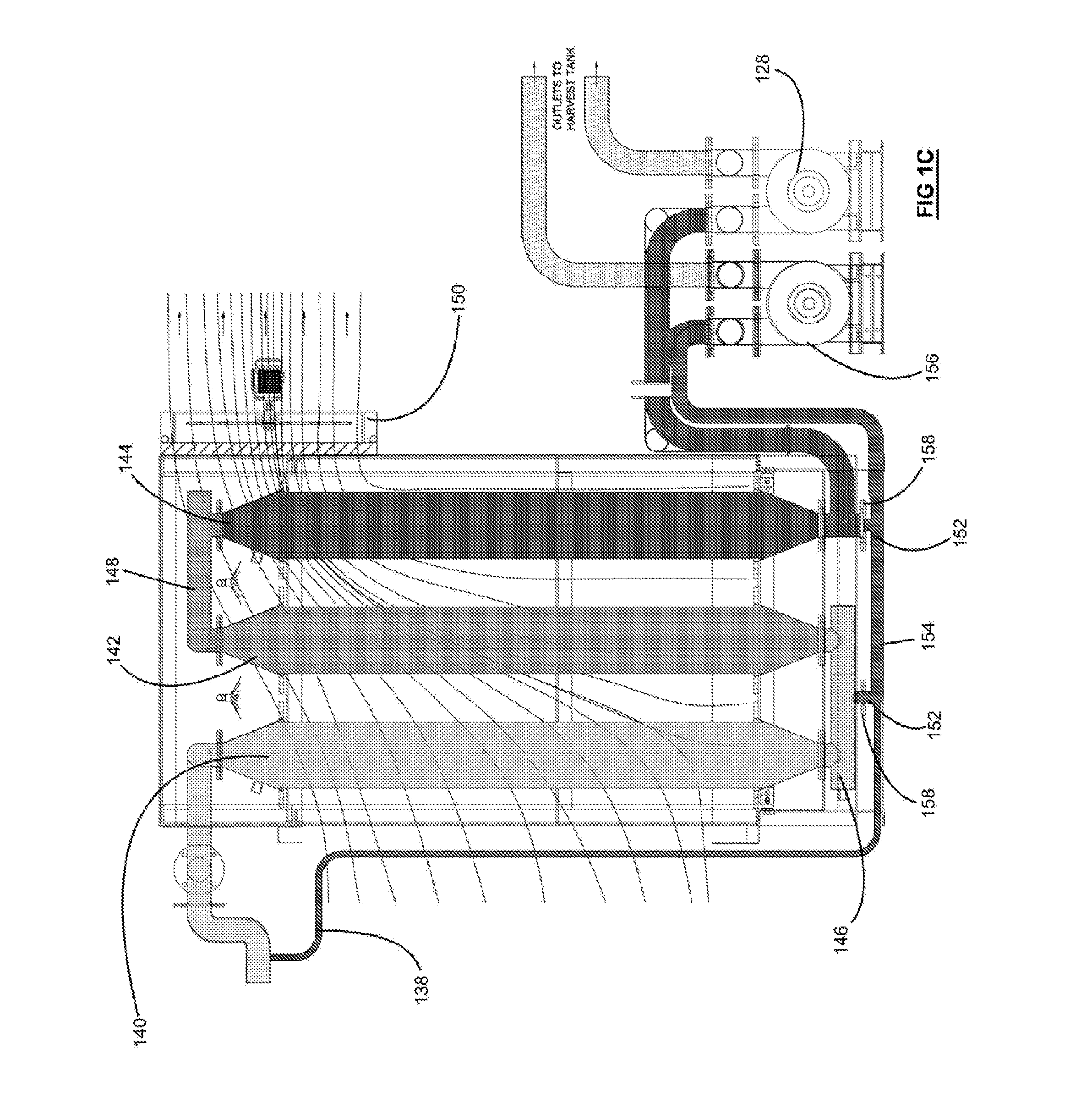
[0161]The apparatuses were operated simultaneously and controlled by a control unit. Each apparatus received a portion of the drill mud from the drill mud tank. In each apparatus, the drill mud was intermittent...


PUM

PropertyMeasurementUnit
Pressureaaaaaaaaaa
Speedaaaaaaaaaa
Timeaaaaaaaaaa

Abstract

An apparatus and process for removing moisture from sludge. The apparatus comprises a housing having an inlet and outlet for respective receipt and discharge of the sludge. A conveyor is located in the housing and is configured to transport the sludge from the inlet to the outlet. The apparatus further comprises a heater to heat the sludge to remove moisture therefrom whilst the sludge is being transported by the conveyor. The apparatus also comprises a vacuum pump arranged to extract air from the apparatus and, at the same time, to cause moisture removed from the sludge to flow therefrom together with the extracted air.

Description

TECHNICAL FIELD[0001]Disclosed are an apparatus and process for the removal of moisture from sludge. The apparatus and process have particular, though not exclusive, application within the treatment of drill mud.BACKGROUND ART[0002]Sludge, made up of solids and liquid, is formed as a by-product of many processes used in a wide range of industries (e.g. mining, food processing, manufacturing, sewage treatment, etc.)[0003]Sludge may be treated at the same location where it is created or it may be transported to an alternative location for treatment or disposal. Environmental considerations and / or specialist sludge processing requirements often determine where and how the sludge is treated and disposed of.[0004]One example of sludge that requires treatment is in the drilling industry, where drill muds are created as a by-product during and after the drilling process. Drill mud is often considered contaminated waste and must be processed prior to being re-integrated with the environment...

Claims


Application Information

Patent Timeline
IPC IPC(8): C02F11/12B01D1/00F26B21/06F26B17/02F26B17/04B01D1/20B01D5/00C02F11/121C02F11/13
CPCF26B5/041F26B2200/18C02F11/12C02F2301/063F26B17/20B01D1/0041F26B21/06F26B17/023C02F2103/10C02F11/121B01D5/006B01D1/20F26B17/04E21B21/065C02F11/13
Inventor MCPHERSON, JASON
Owner ALI JAK HLDG
Learn More