
Multilayer coating for a component

a multi-layer coating and component technology, applied in the direction of superimposed coating process, machine/engine, corrosion prevention fuel injection, etc., can solve the problems of plunger/check seat wear and tear, and seat wear and tear

Inactive Publication Date: 2016-08-11
CATERPILLAR INC
View PDF4 Cites 13 Cited by
  • Summary
  • Abstract
  • Description
  • Claims
  • Application Information

AI Technical Summary

Benefits of technology

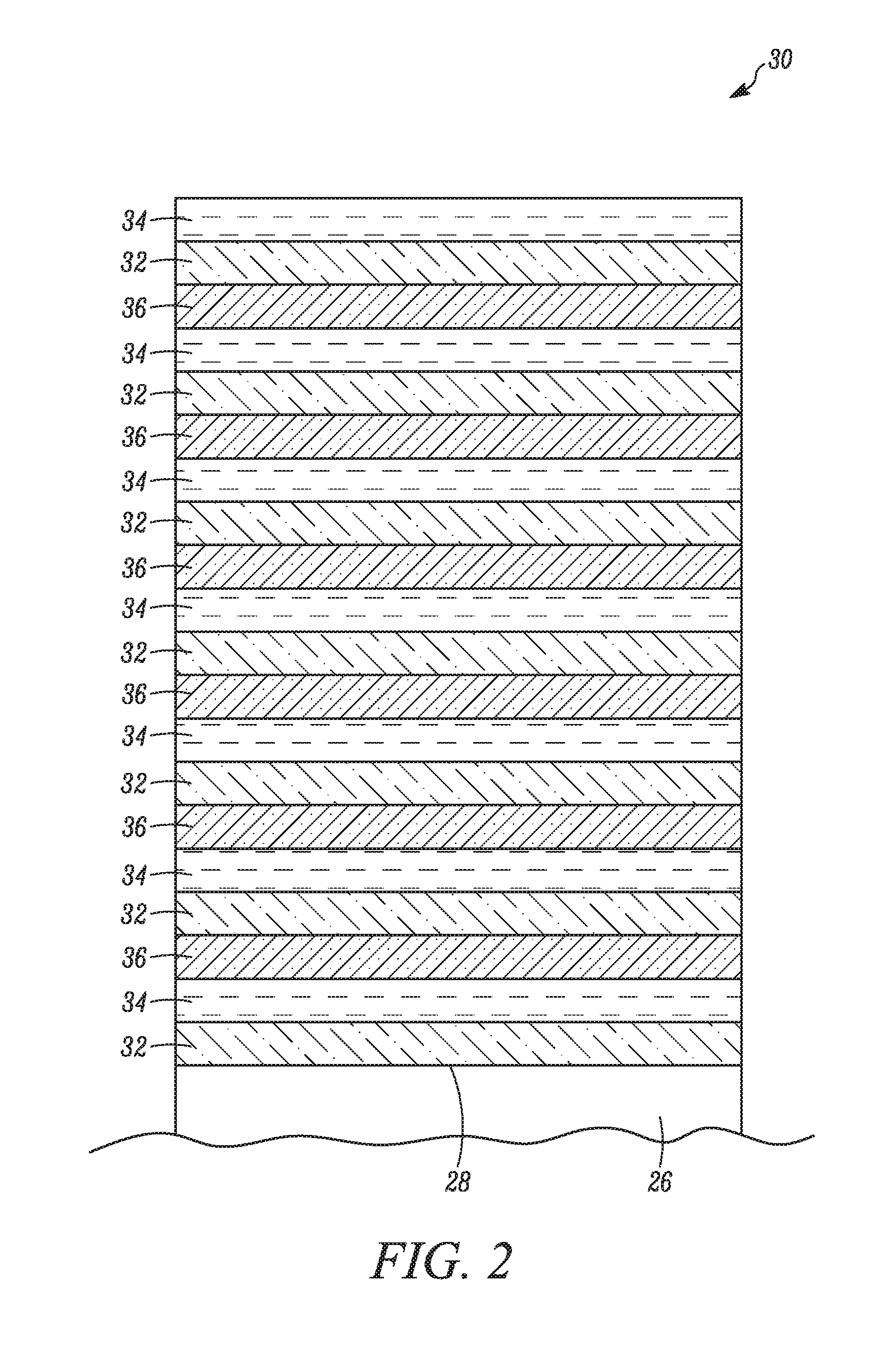
The present disclosure provides a multilayer coating for a metallic surface of a component. This coating includes three layers: a first layer of metal nitride, a second layer of metal, and a third layer of diamond-like carbon (DLC) material. The three layers differ in their hardness, elasticity, corrosion resistance, and lubricity. The coating is applied in a repeating sequence with at least ten layers. The technical effects include improved wear resistance, corrosion resistance, and lubricity of the metallic surface.

Problems solved by technology

When the fuel injection process may need to be stopped, the plunger / check may come back to its idle position with considerable force and may rest on the seat thus closing the passage.
This movement of the plunger / check may create continuous impacts on the seat when the plunger / check may contact the seat.
As a result, the plunger / check and / or the seat may experience accelerated wear and tear in the form of erosion, scuffing, chipping, and so on.
Additionally, a pressure and a velocity of the fuel passing across the plunger / check and the seat may also be considerably high to cause wear and tear of the plunger / check and / or the seat.
Generally, properties of the multilayer coating may not be sufficient to resist erosion and / or crack propagation in heavy duty engine components such as the plunger / check.

Method used


Image

  • Multilayer coating for a component
  • Multilayer coating for a component
  • Multilayer coating for a component

Examples


Embodiment Construction

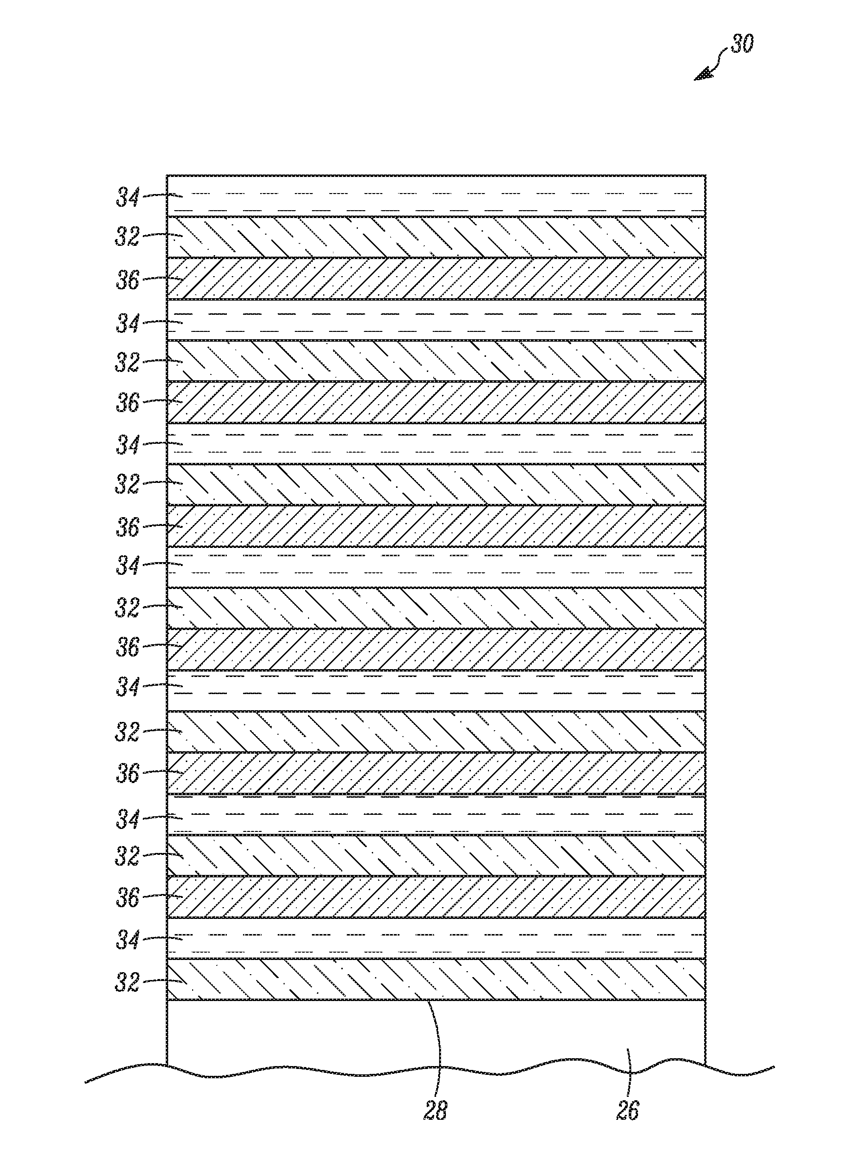
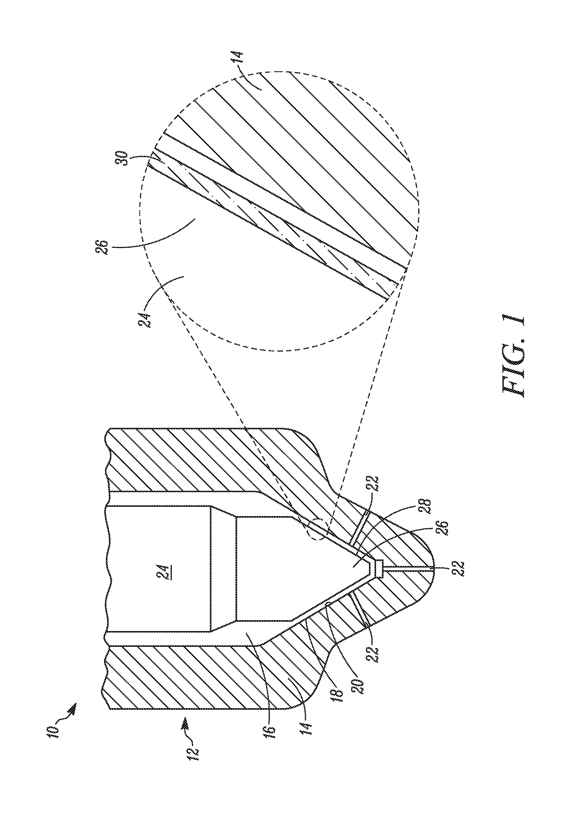
[0010]Wherever possible, the same reference numbers will be used throughout the drawings to refer to the same or the like parts. Referring to FIG. 1 an exemplary component 10 is illustrated. More specifically, the component 10 is a fuel injector 12. In other embodiments, the component 10 may be any component such as a valve, a pump, a bearing, and so on.

[0011]The fuel injector 12 is configured to inject fuel wider high pressure in to one or more cylinders of an engine (not shown). The fuel injector 12 includes a body 14 having an elongate and hollow configuration defining a passage 16. The passage 16 is configured to provide a path for a flow of the fuel through the fuel injector 12. The body 14 further includes a seat 18. The seat 18 includes a conical configuration defining an inner surface 20. The body 14 includes one or more apertures 22 provided on the seat 18. The apertures 22 are configured to inject the fuel from the passage 16 into the cylinder. The body 14 and the seat 18 ...


PUM

PropertyMeasurementUnit
thicknessaaaaaaaaaa
thicknessaaaaaaaaaa
metallicaaaaaaaaaa

Abstract

A multilayer coating for a metallic surface of a component is provided. The multilayer coating includes a first coating having a metal nitride. The first coating at least partially overlaps the metallic surface. The multilayer coating also includes a second coating having a metal. The second coating at least partially overlaps the first coating. The multilayer coating further includes a third coating having a Diamond Like Carbon (DLC) material. The third coating at least partially overlaps the second coating. The first coating, the second coating, and the third coating differ from one another with respect to at least one of hardness, elasticity, corrosion resistance, and lubricity. The multilayer coating includes at least ten overlapping layers having successive layers of the first coating, the second coating, and the third coating in repeating sequence.

Description

TECHNICAL FIELD[0001]The present disclosure relates to a multilayer coating for a component. More specifically, the present disclosure relates to the multilayer coating to protect a metallic surface of the component from wear and tear.BACKGROUND[0002]Internal combustion engines running on diesel fuel employ pumps, valves and / or fuel injectors for injecting fuel at high pressure in to the cylinders for combustion. The fuel injector includes a plunger / check which, in idle position, rests against a seat of the injector. During operation, when the fuel may be required to be injected in to the cylinder, the plunger / check may move away from the seat, thus, opening a passage for the fuel to enter the cylinder via the seat. When the fuel injection process may need to be stopped, the plunger / check may come back to its idle position with considerable force and may rest on the seat thus closing the passage.[0003]Typically, depending on engine parameters, the plunger / check may translate with re...

Claims


Application Information

Patent Timeline
Patent Type & Authority Applications(United States)
IPC IPC(8): C23C16/26C23C14/06C23C16/44C23C14/22C23C16/30C23C16/06
CPCC23C16/26C23C16/30C23C16/06C23C14/0605C23C14/22C23C14/0641C23C16/44C23C28/32C23C28/34C23C28/343C23C28/42F02M59/445F02M61/166F02M2200/02F02M2200/05F02M2200/9038
Inventor FLANNERY, COLM MARTINTAYLOR, STEVEN CHARLESFENG, BAOBERG, LUCY VICTORIASULLIVAN, JOSEPH RYAN
Owner CATERPILLAR INC
Learn More