Few mode optical fiber links for space division multiplexing

a technology of optical fiber and space division, applied in the field of fiber optic transmission, can solve the problems of affecting the use of multimode fibers in the long distance communication scenario, major limitations on fiber transmission capacity, and single-mode fibers suffering from nonlinear problems, and achieve the effect of easy manufacturing and low cos

Active Publication Date: 2016-08-11
DRAKA COMTEQ BV
View PDF15 Cites 22 Cited by
  • Summary
  • Abstract
  • Description
  • Claims
  • Application Information

AI Technical Summary

Benefits of technology

[0045]Such an alternate graded-index trench-assisted profile allows meeting the core criterion and the trench criterion set forth in an embodiment of the invention. Moreover, such a few-mode fiber is easy to manufacture and costs little. The inner cladding layer may either have a negative or a positive refractive index difference with the core.

Problems solved by technology

However, single-mode fibers suffer from nonlinearly problems, which are major limitations on fiber transmission capacity.
However, such fiber designs unfortunately enhance modal coupling, which impedes the use of multimode fibers in the long distance communication scenario.
This optimization, however, becomes more and more difficult when the number of LP modes increases.
However, according to this first known solution, the core and cladding support only the LP01 and LP11 modes at wavelengths greater than 1500 nm, which is a too small number of modes compared to the increasing demand on per-fiber transmission capacity.
Although such designs are promising, they do not allow reducing the Differential Mode Group Delays as much as desired, and therefore induce limits in the transmission system reach.
In addition, the profiles disclosed in both documents are not optimized to ensure low bend losses and high leakage losses, which, however, are important issues for FMFs.
Actually, none of the known documents relating to FMFs addresses the issue of designing a few-mode fiber showing low bend losses and high leakage losses.
However, these designs might be sensitive to small variations that can occur during the manufacturing process, such as profile variations, radius variations or refractive index difference variations for example.
It is indeed very difficult to repeatedly manufacture optical fibers, which perfectly show the theoretical features, which were aimed at.

Method used


Image

  • Few mode optical fiber links for space division multiplexing
  • Few mode optical fiber links for space division multiplexing
  • Few mode optical fiber links for space division multiplexing

Examples


first embodiment

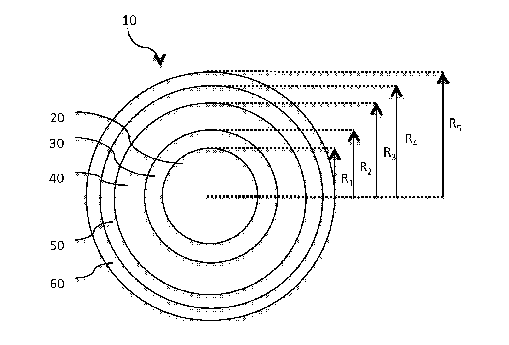
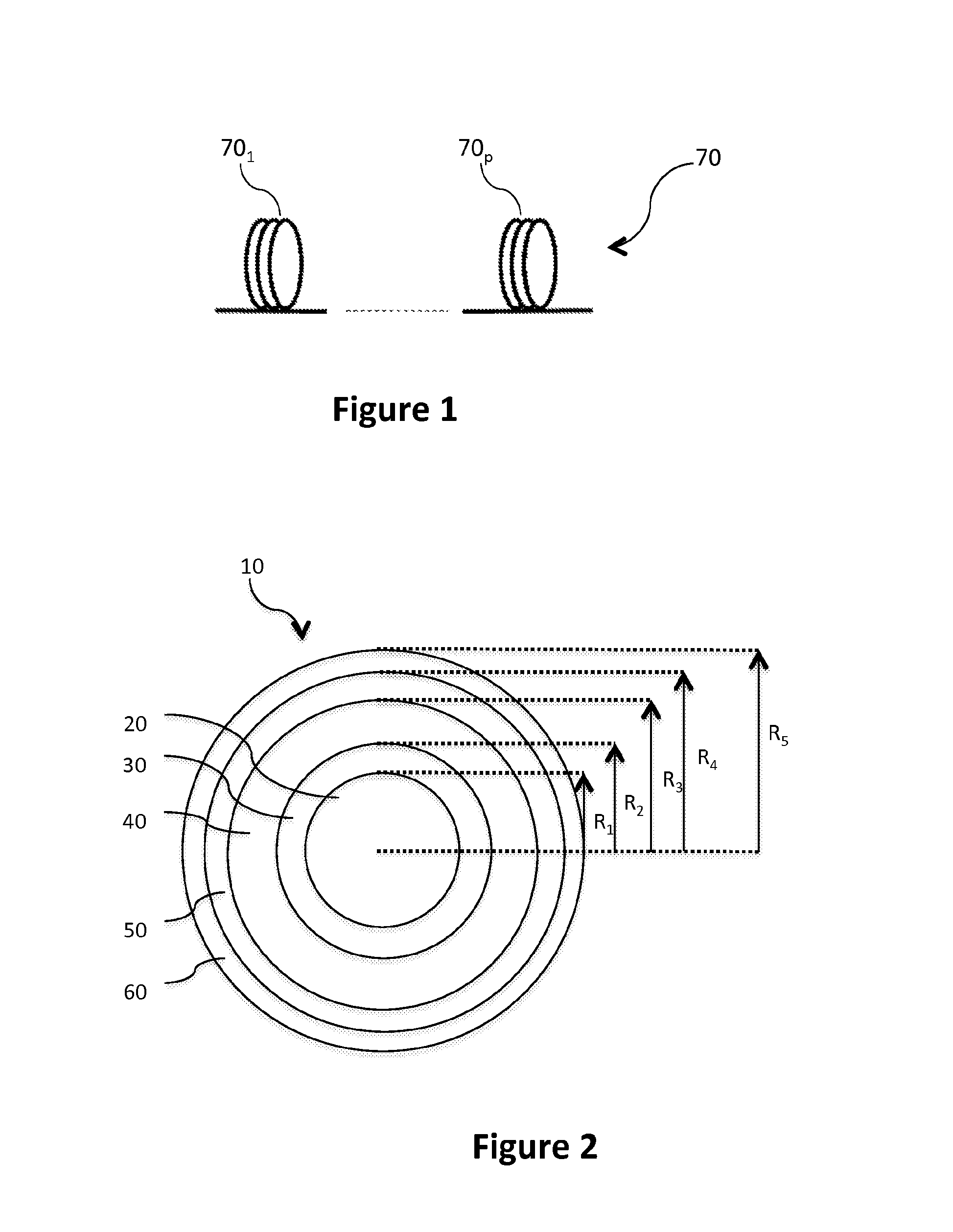
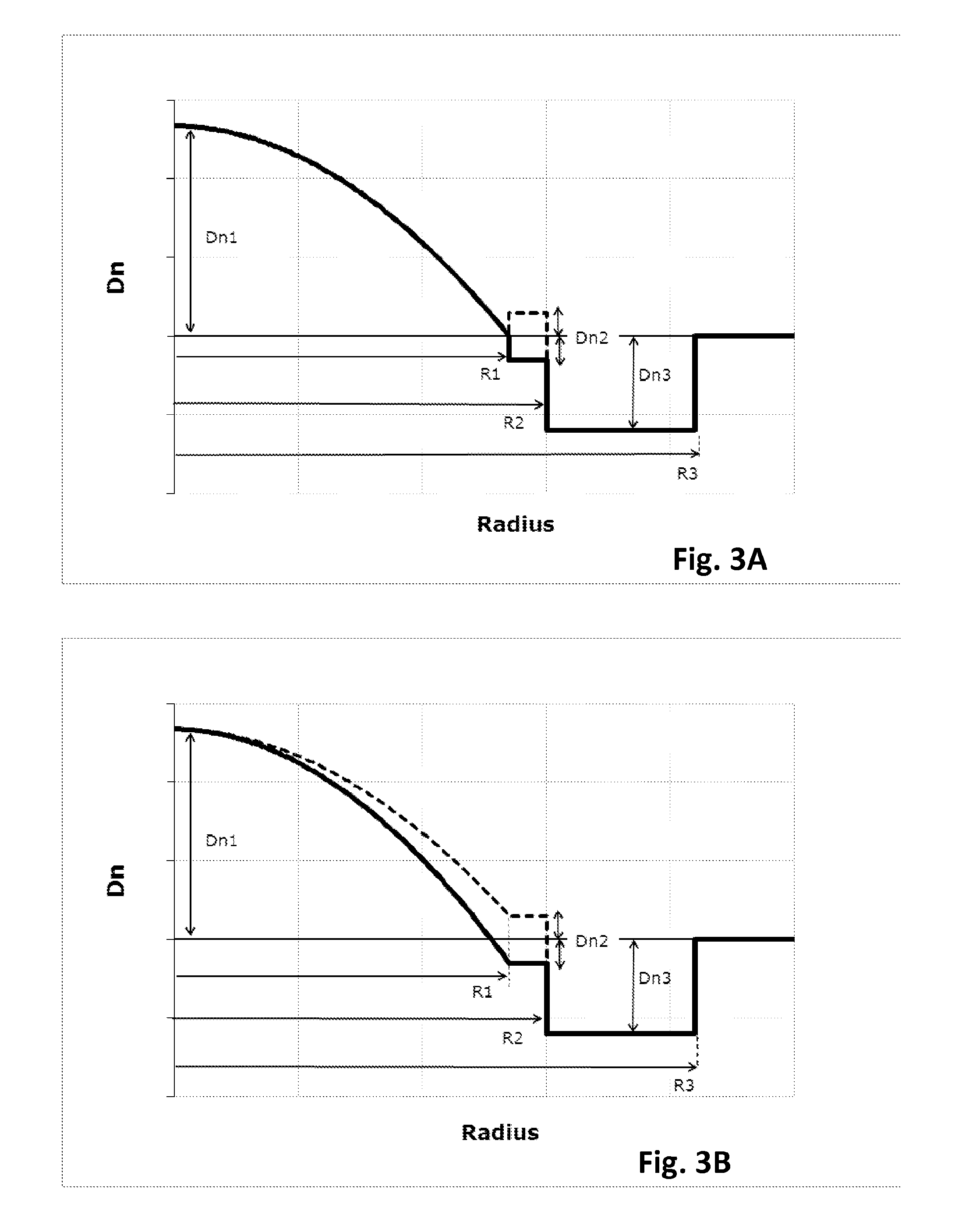
[0072]FIG. 3A depicts the refractive index profile n(r) of optical fiber 10 according to the invention. It describes the relationship between the refractive index value n and the distance r from the center of the optical fiber. The x-axis represents radial position with x=0 representing the center of the core region, and the y-axis represents refractive index, expressed as an index difference Dn unless otherwise stated.

[0073]According to embodiments of the invention, it is possible that only one, or several, or all, or even none of the optical fibers making up an optical link according to the invention show the refractive index of FIG. 3A.

[0074]In that first embodiment, the optical fiber 10 has an optical core 20 having a refractive index profile n(r) defined as follows:

n(r)=n0·1-2·Δ·(rR1)αr≤R1

where:

r is a variable representative of the radius of the optical fiber,

R1 is the optical core radius,

Δ is the normalized refractive index difference, with

Δ=n02-n122n02

n1 is the minimal refrac...

second embodiment

[0084]FIG. 3B depicts the refractive index profile n(r) of an optical fiber according to the invention. Once again, there may be embodiments of the invention where only one, or several, or all, or even none of the optical fibers in said optical link show the profile of FIG. 3B.

[0085]Such a profile differs from that of the first embodiment in that the minimal refractive index of the core n1 is not equal to the refractive index of the outer cladding nCl but may either show a negative or a positive (shown in dashed lines on FIG. 2B) refractive index difference with respect to the optical fiber outer cladding. In case the cladding comprises an inner cladding layer 30, the minimal refractive index of the core n1 is equal to the constant refractive index of the inner cladding n2, which may either show a negative or a positive (shown in dashed lines on FIG. 2B) refractive index difference Dn2=n2−nCl with respect to the optical fiber outer cladding.

[0086]Like in the first embodiment, the ou...

third embodiment

[0088]FIG. 3C depicts the refractive index profile n(r) of an optical fiber according to the invention. Once again, there may be embodiments of the invention where only one, or several, or all, or even none of the optical fibers in said optical link show the profile of FIG. 3C.

[0089]In this third embodiment, the inner cladding layer 30 is an extension of the graded index core 20, such that both the optical core 20 and the inner cladding layer 30 have a refractive index profile n(r) defined as follows:

n(r)=n0·1-2·Δ·(rR2)αr≤R2

where:

r is a variable representative of the radius of the optical fiber,

R2 is the outer radius of the inner cladding layer 30,

Δ is the normalized refractive index difference, with

Δ=n02-n122n02

n1 is the minimal refractive index of the inner cladding layer (i.e. the refractive index at radius R2),

n0 is the maximal refractive index of the optical core,

α is a non-dimensional parameter that defines the index profile shape of both the optical core and the inner claddin...


PUM


Abstract

The invention relates to an optical link comprising N optical fibers, with N≧2. Each optical fiber comprises an optical core and an optical cladding surrounding the optical core, the optical core having a single αi graded-index profile with αi≧1, and the optical core having a radius R1i, where i E [1; N] is an index designating said optical fiber. Said optical cladding comprises a region of depressed refractive index ntrenchi, called a trench, surrounding the optical core. According to embodiments of the invention, for all optical fibers in said link, said optical core radius R1i and said length Li are chosen such that R1i≧13.5 μm and so as to satisfy a criterion C of quality. Thus, the invention provides a few-mode optical fiber link, which allow guiding an increased number of LP modes as compared to prior art FMF links, while reaching low Differential Mode Group Delay.

Description

1. FIELD OF THE INVENTION[0001]The invention relates to the field of fiber optic transmission, and, more specifically, to improved few-mode optical fiber links for space division multiplexing.2. BACKGROUND[0002]An optical fiber is conventionally constituted of an optical core, which transmits an optical signal, and of an optical cladding, which confines the optical signal within the optical core. To that end the refractive index of the core, nC, is greater than the one of the cladding, nCl. An optical fiber is generally characterized by a refractive index profile that associates the refractive index (n) with the radius (r) of the optical fiber: the distance r with respect to the center of the optical fiber is shown on x-axis and the difference Dn between the refractive index at radius r, n(r), and the refractive index of the optical cladding nCl is shown on y-axis.[0003]Nowadays, two main categories of optical fibers exist: multimode fibers and single-mode fibers. In a multimode fib...

Claims


Application Information

Patent Timeline
Patent Type & Authority Applications(United States)
IPC IPC(8): G02B6/028G02B6/02H04J14/04G02B6/036
CPCG02B6/02023G02B6/0288G02B6/03627G02B6/02214H04J14/00H04J14/04G02B6/0365
Inventor SILLARD, PIERREMOLIN, DENISBIGOT-ASTRUC, MARIANNE
Owner DRAKA COMTEQ BV
Why Eureka
Try Eureka