Capacitor discharge circuit for power supply EMI filters

a technology of capacitor discharge circuit and power supply, applied in the direction of power conversion systems, electrical apparatus, etc., can solve the problems of ac input voltage or rectified ac voltage drift over time, and the comparison to a constant or fixed reference may not provide an accurate measure of input ac voltage, so as to achieve less susceptible to noise or instability

Active Publication Date: 2016-08-18
BCD SHANGHAI MICRO ELECTRONICS CO LTD
View PDF1 Cites 15 Cited by
  • Summary
  • Abstract
  • Description
  • Claims
  • Application Information

AI Technical Summary

Benefits of technology

[0008]According to embodiments of the present invention, a discharging circuit is configured to discharge the X-capacitors in a controlled manner when the AC input voltage is stopped. The presence of the AC input voltage is detected by comparing a sampled rectified AC input voltage with a time-varying signal derived from a signal-shaping circuit. The AC voltage sensing circuit in embodiments of the invention provides margins to small changes or ripples either at high or low voltages of the rectified input signal Vb. As a result, the AC voltage sensing circuit in embodiments of the invention are less susceptible to noise or instability in the input AC voltage compared with conventional designs.

Problems solved by technology

The inventors have observed that the conventional methods described above for reducing power loss from the discharging resistor suffer from many limitations.
However, the AC input voltage or rectified AC voltage can drift over time.
Therefore, comparing to a constant or fixed reference may not provide an accurate measure of the state of the input AC voltage.
Thus, the performance of the power supply can be susceptible to the instability of the line voltage.
Moreover, the conventional designs often involve complicated circuits that cause the power supply less cost-effective.
Further, it is often challenging for conventional designs to meet more stringent requirements.

Method used


Image

  • Capacitor discharge circuit for power supply EMI filters
  • Capacitor discharge circuit for power supply EMI filters
  • Capacitor discharge circuit for power supply EMI filters

Examples


Embodiment Construction

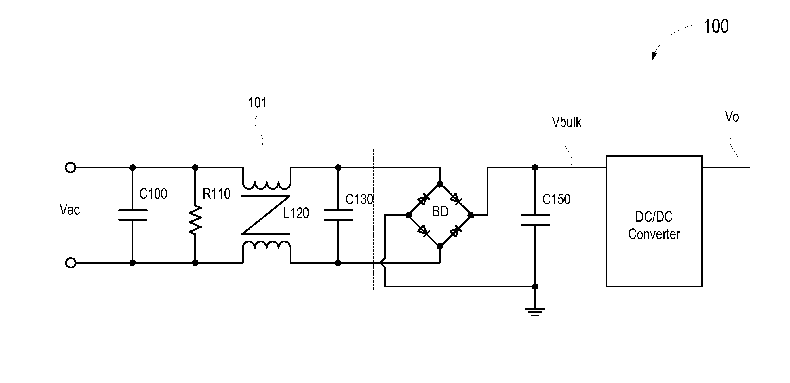
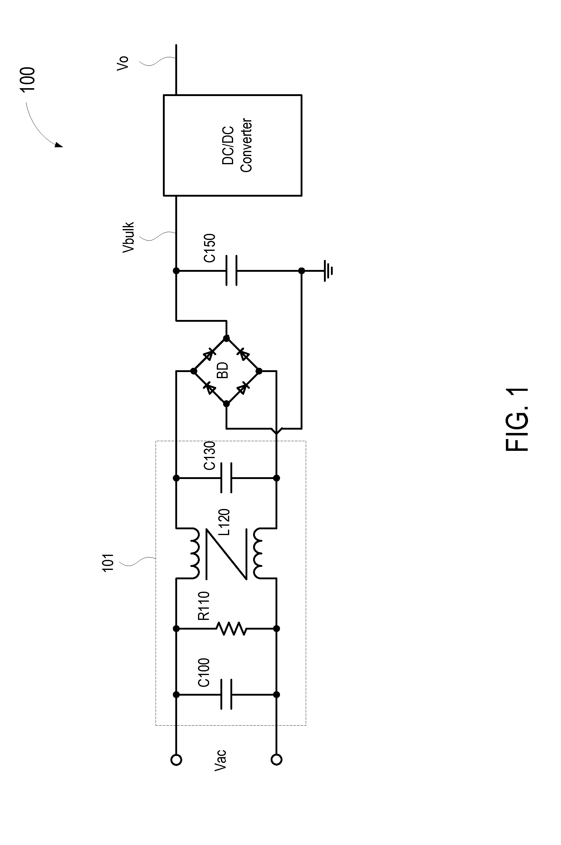
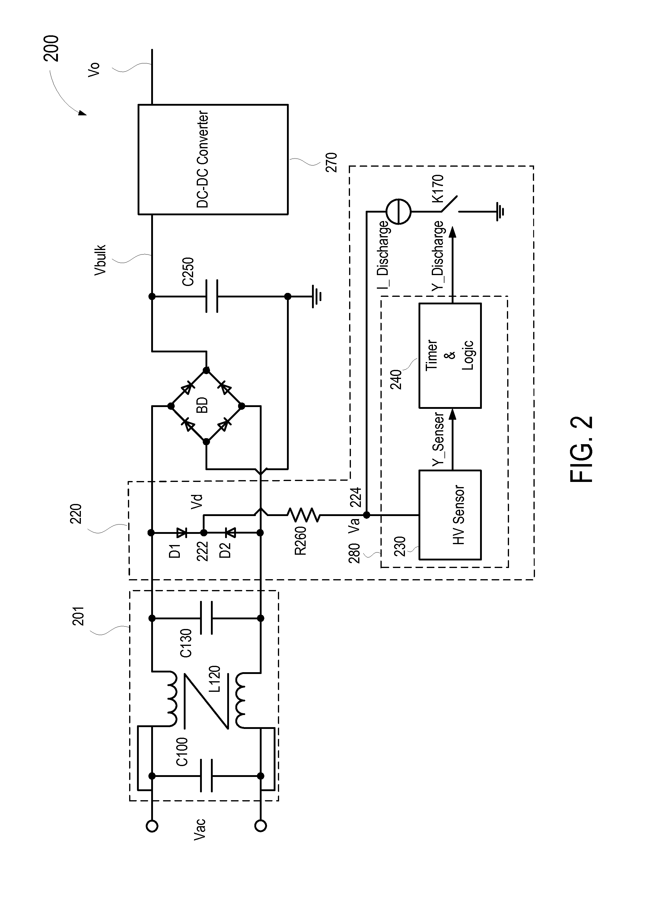
[0030]FIG. 2 is a simplified schematic diagram illustrating an AC-DC power supply system according to an embodiment of the present invention. As shown in FIG. 2, power supply system 200 includes an input filter 201, a bridge diodes BD, an input capacitor C250, an DC-DC converter 270. Depending on the embodiments, converter 270 can be any suitable power converters, including PFM (pulse frequency modulation) or PWM (pulse width modulation) converters. Input filter 201 is similar to input filter 101 shown in FIG. 1 for reducing EMI, and includes a first X-capacitor C100, a second X-capacitor C130, and an inductor L120. However, discharging resistor R110 in FIG. 1 is replaced by a discharging circuit 220 in FIG. 2 that is configured to detect AC line voltage in real time and to discharge current from the X-capacitor within a given time when the input AC power is stopped. This condition can arise, for example, when a power supply is unplugged from the power outlet. The discharging circui...


PUM


Abstract

A discharging circuit for a power supply includes a rectifying circuit for coupling to an input filter capacitor coupled to an AC input voltage for providing a rectified AC voltage. A discharge resistor is coupled to the rectifying circuit, and a power switch and a discharging current source are coupled in series with the discharging resistor. A discharge control circuit is coupled to the discharge resistor for providing a discharge signal to cause the power switch to turn on for discharging the capacitor using the discharging current source. The discharging control circuit includes an AC voltage sampling circuit for providing a sampled rectified voltage, a signal-shaping circuit for providing a time-varying signal derived from the sampled rectified voltage, a comparator circuit for comparing the sampled rectified voltage and the time-varying signal, and a counter circuit for providing the discharge signal in response to an output of the comparator circuit.

Description

CROSS-REFERENCES TO RELATED APPLICATIONS[0001]This application claims priority to Chinese Patent Application No. 201410421183.4, filed on Aug. 25, 2014 and Chinese Patent Application No. 201420481112.9, filed on Aug. 25, 2014, both of which are incorporated herein by reference in their entirety.BACKGROUND OF THE INVENTION[0002]The present invention relates generally to the field of switch mode power supply (SMPS). More particularly, embodiments of the present invention relate to circuits for discharging input capacitors in SMPS.[0003]Switched-mode AC-DC converters are widely used to provide stable power to home appliances, computers, communicating devices and so on. Switch mode power supplies have many advantages, including smaller volume, better stability, and higher power efficiency. As SMPS finds wide spread applications in portable consumer electronics, more emphasis has been placed on performance issues such as electromagnetic interference (EMI) protection and standby power. Fo...

Claims


Application Information

Patent Timeline
Patent Type & Authority Applications(United States)
IPC IPC(8): H02M1/44
CPCH02M1/44H02M1/322
Inventor ZHAO, AN DONGYING, ZHENG
Owner BCD SHANGHAI MICRO ELECTRONICS CO LTD
Why Eureka
Try Eureka