Magnetic mount for blasting equipment and related methods

a magnetic mount and blasting equipment technology, applied in the direction of cleaning heat-transfer devices, flush cleaning, cleaning using liquids, etc., can solve the problems of reducing the efficiency of heat transfer through the heat exchanger, affecting the safety of operators, scaling or excessive residue and buildup, etc., to achieve the effect of enhancing the safety of operators

Inactive Publication Date: 2016-08-25
PSI PRESSURE SYST
View PDF4 Cites 30 Cited by
  • Summary
  • Abstract
  • Description
  • Claims
  • Application Information

AI Technical Summary

Benefits of technology

[0007]A water blasting apparatus and related method are provided to enhance the safety of an operator engaged in cleaning certain equipment and structures. In one embodiment, the apparatus can include a track, a connector moveable along the track, and a water blasting device adapted to shoot water at a pressure above 1000 psi, joined with the connector. One or more high strength magnets join the track with a ferromagnetic structure, such as the equipment or structure itself or facility framework near the equipment, thereby holding the track in a fixed orientation relative to the equipment or structure to be cleaned.
[0012]In a further embodiment, first and second magnets can be pivotally joined with each opposing end of the track. Each magnet can be attached to separate and spaced apart ferromagnetic structures adjacent or on the equipment to be cleaned. The magnets can effectively secure the ends to two locations, thereby positioning the track, and thus the water blasting equipment in a fixed orientation relative to the equipment or structure.
[0014]In yet a further embodiment, the tractor can include an actuator adapted to engage a holder or bracket contacting the water blasting device. The actuator can effectively move the holder, thereby reorienting the nozzle in varying directions to clean or blast a particular area. Due to the restraint of the device by the connector and track, its movement can be limited to a particular area of cleaning until the control unit moves the tractor again with the water blasting device.
[0015]In even a further embodiment, the method can include connecting the water blasting device to the track, magnetically coupling the track to a ferromagnetic structure so that the nozzle is proximal the equipment to be cleaned, and so that the elongated track is maintained in a fixed orientation, and shooting water at high pressure toward the equipment, while safely restraining the water blasting device.
[0019]With the current embodiments of the water blasting apparatus and method, improved levels of safety for operators can be realized. Where the track and connector constrain a water blasting device for movement within a limited area to clean equipment, the water blasting device can be less likely to become loose and violently thrash around, thereby presenting a danger to the operator. With the water blasting device attached to the track and oriented in a specific manner, an operator can consistently and methodically clean a surface of certain equipment. This can result in faster cleaning times, as well as reduced power consumption and man hours. Where the track includes first and second magnetics attached to ends of the track, the track can be highly modifiable to fit a variety of configurations and spaces near equipment to be cleaned. For example, the track can be extended in length to accommodate structures, to which the magnets are attached, that are spaced apart from one another. The track also can be oriented vertically, horizontally or in various other planes, all depending on the location of the magnets coupling the device to structures surrounding the equipment. Further, given the variable length of the track, the apparatus can be quickly and efficiently positioned in confined spaces or large spaces. Where the apparatus includes a sensor, such as a proximity sensor, this can enhance safety for the operator, generally ensuring automatic shutdown of the system upon any decoupling of the track / magnets from a ferromagnetic support structure.

Problems solved by technology

Over time, the bores and exterior walls of the heat exchanger's tubes can corrode, scale or exhibit excessive residue and buildup.
This buildup and / or residue can decrease the efficiency of heat transfer through the heat exchanger.
In turn, operating costs for the heat exchanger can significantly increase.
In all of the above equipment cleaning applications, there are inherent dangers.
For example, the lances typically are difficult to prevent from buckling and / or bending while being guided into a tube.
In cases where the lance is more rigid and adapted to insert into the opening of the pipe, the jet reaction from a high pressure stream shooting from the nozzle can create major safety issues.
Because the water is forced through the nozzle at significant pressures, the jet from the nozzle can frequently blow backward, striking the operator.
In other cases, if an operator becomes fatigued and accidentally drops the water blasting lance, it sometimes can violently thrash around under the propulsion of the jet stream.
This can increase the likelihood that the device will become loose and violently thrash around.
In all of the above cases, there is an issue with the water blasting lances being manually handled by the users.
There can be a high propensity for accidents to occur when those devices unintentionally depart from the user's hands.
These assemblies, however, require the labor intensive bolting of a complex frame around the heat exchanger to properly index the lance relative to the tubes of the heat exchanger to be cleaned.
The extra effort to bolt on the frame can be particularly cumbersome and time consuming.

Method used


Image

  • Magnetic mount for blasting equipment and related methods
  • Magnetic mount for blasting equipment and related methods
  • Magnetic mount for blasting equipment and related methods

Examples


Embodiment Construction

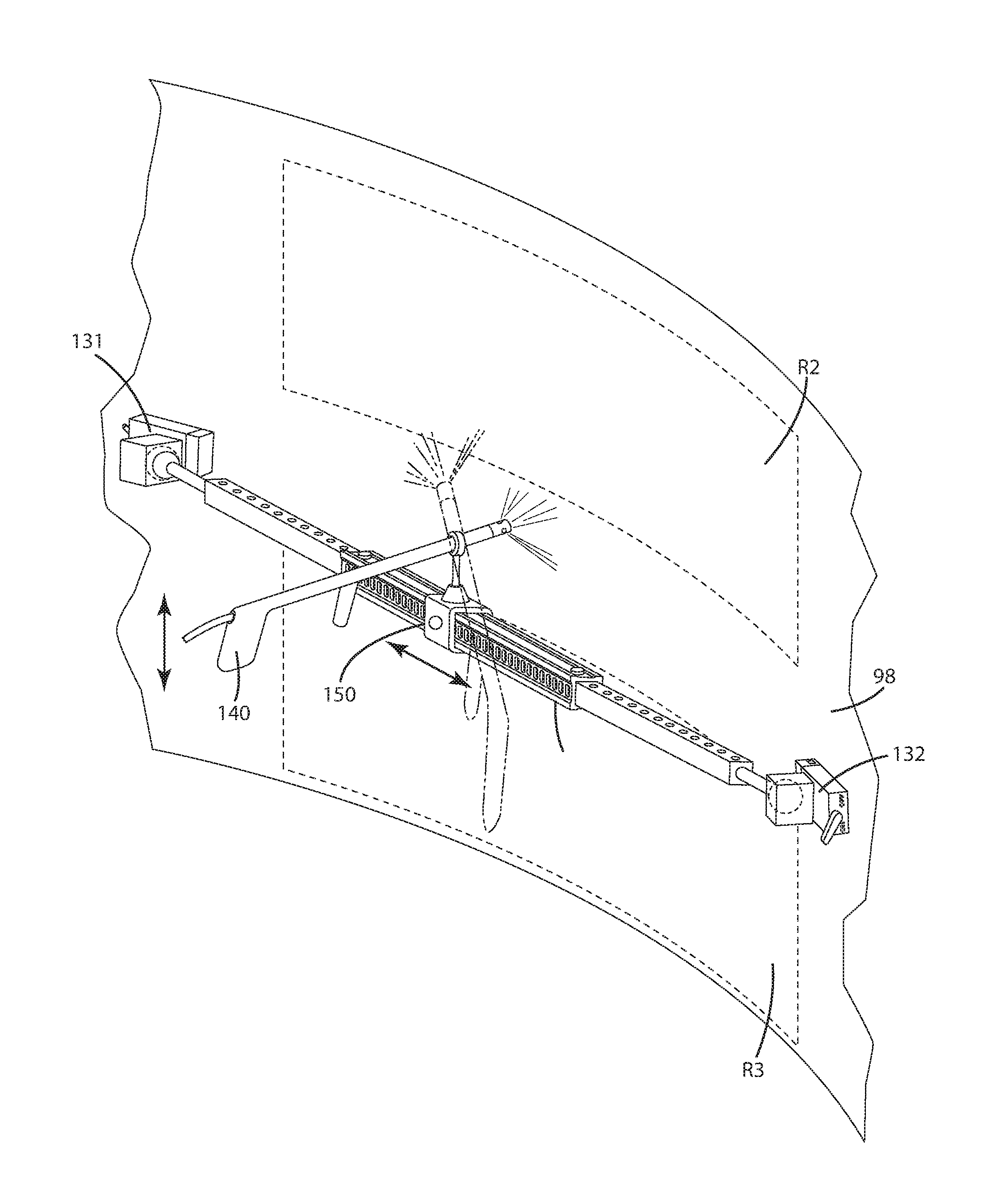
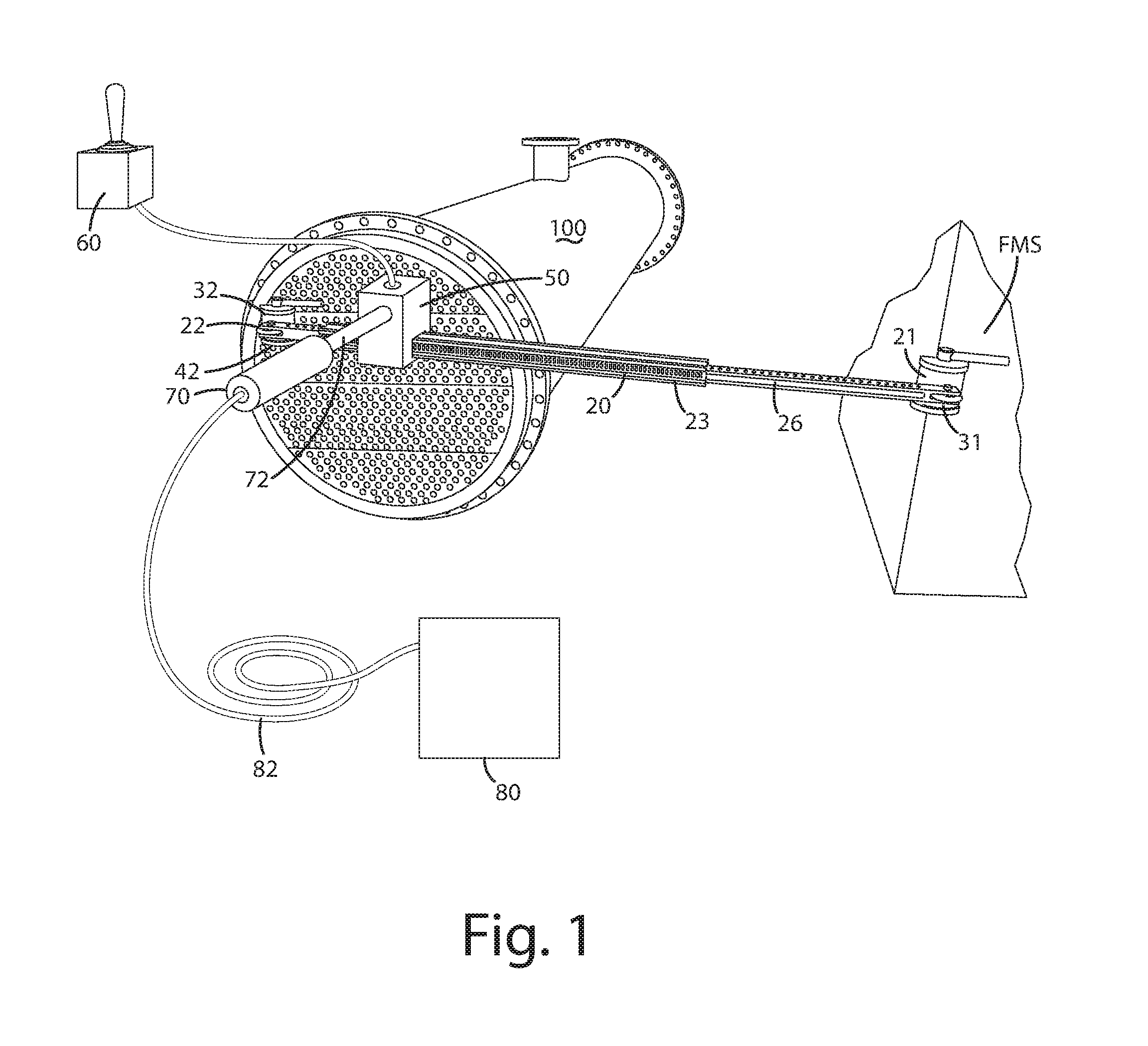
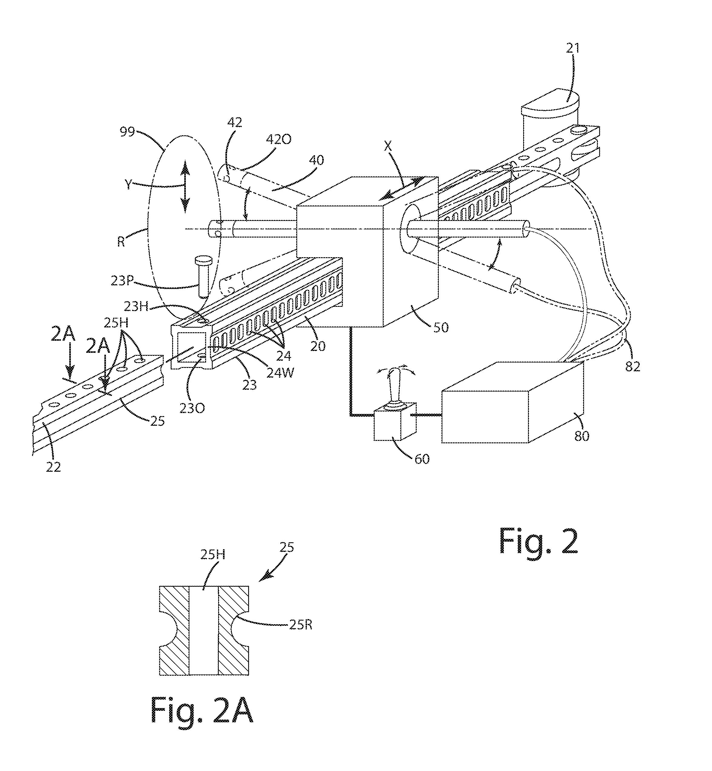
[0034]A water blasting apparatus and related method in accordance with the current embodiment is illustrated in FIGS. 1-6 and generally designated 10. The water blasting apparatus can be used to clean a heat exchanger as shown in connection with the current embodiment. Of course, the apparatus can be modified to be used in conjunction with cleaning other equipment, such as piping as shown in the first alternative embodiment and / or a tank as shown in the second alternative embodiment below. Further alternatively, the apparatus herein can be used to high pressure water blast other equipment or structures such as falling pressure evaporators, towers, piping, containers, bins, molds, impellers, mining equipment, watercraft, and a variety of other equipment or structures. Thus, it should be understood that the current embodiments are not limited to equipment associated with cleaning heat evaporators, although that is what is primarily illustrated in the current embodiment.

[0035]Generally...


PUM


Abstract

A water blasting apparatus and related method are adapted to clean equipment. The apparatus includes a track having telescoping rails, a connector moveable along the track, and a water blasting device adapted to shoot water at a pressure above 1000 psi, joined with the connector. One or more rare earth magnets join the track with a ferromagnetic structure, thereby holding it in a fixed orientation relative to the equipment to be cleaned. The apparatus can include a proximity sensor to ensure the track is adequately anchored, and an auto shut-off system when it is not. The method can include connecting the water blasting device to the track, magnetically coupling the track to a structure so that the nozzle is proximal equipment, and so that the elongated track is maintained in a fixed orientation, and shooting water at high pressure toward the equipment, while safely restraining the water blasting device.

Description

BACKGROUND OF THE INVENTION[0001]The present invention relates to water blasting equipment and more particularly to high pressure water blasting devices adapted to clean equipment such as heat exchangers, falling pressure evaporators, storage tanks, tubes, piping, towers and similar equipment.[0002]There are a variety of industrial piping systems using in conjunction with different industries, such as, chemical processing, recycling, polymer forming, oil and gas refining and other industries. These industrial piping systems frequently require cleaning, resurfacing, painting and / or coating. As an example, in the oil refining industry, special equipment such as heat exchangers and evaporators are utilized. Over time, the bores and exterior walls of the heat exchanger's tubes can corrode, scale or exhibit excessive residue and buildup. This buildup and / or residue can decrease the efficiency of heat transfer through the heat exchanger. In turn, operating costs for the heat exchanger can...

Claims


Application Information

Patent Timeline
Patent Type & Authority Applications(United States)
IPC IPC(8): B08B9/032B08B9/043F28G15/00F28G9/00F28G15/02F28G15/04B08B3/02B08B9/08
CPCB08B9/0325B08B3/024B08B9/0433F28G15/003F28G9/00F28G15/02F28G15/04B08B9/0813F28D7/16F28G1/163F28G15/08
Inventor SHAWVER, TODD A.
Owner PSI PRESSURE SYST
Why Eureka
Try Eureka