Eureka AIR delivers breakthrough ideas for toughest innovation challenges, trusted by R&D personnel around the world.

Recoil attenuating mechanism for a firearm

a recoil attenuating mechanism and recoil technology, applied in the field of recoil attenuating mechanism of firearms, can solve the problems of pronounced muzzle climb, unfavorable use, and difficult to achieve significant increase in mass to counter the recoil action, etc., to achieve the effect of reducing muzzle climb, attenuating recoil, and improving accuracy

Active Publication Date: 2016-08-25
SKYCHASE HLDG CORP
View PDF2 Cites 4 Cited by
  • Summary
  • Abstract
  • Description
  • Claims
  • Application Information

AI Technical Summary

Benefits of technology

The present invention is a recoil attenuating mechanism for semi-automatic pistols that improves accuracy, recovery time, and controllability. It achieves this by redirecting and manipulating the forces of the recoil of the slide of the pistol to a different axis than what is the norm on a regular Browning action, and thus reducing muzzle climb and attenuating recoil. This new action creates a backward and downward force that will limit muzzle climb and redistribute the recoil forces to lower parts of the pistol frame. The invention also includes a method for recoil attenuation.

Problems solved by technology

Furthermore, the gases created during the combustion action of the powder in the barrel will move the muzzle part of the gun in the direction of least resistance, which usually means that it causes a pronounced muzzle climb during the recoil action of the pistol after a shot is fired (cf. FIGS. 3b and 3c), especially where the pistol is chambered with a modern high energy caliber.
This renders the pistol less controllable and less accurate than desired.
In addition, due to the generally preferable relatively small size of automatic pistols, a significant increase in mass to counter the recoil action is generally not easily attainable and is undesirable.
These systems work in varying degrees of efficiency, but each has its major drawbacks.
One example of such a system is the muzzle break: while well designed muzzle brake systems can effectively limit muzzle Climb, they render the pistol very loud, with a significant flash in front of the front sight, not to mention a significant added weight and bulk on the front top end of the pistol.
This makes the pistol cumbersome to use, and basically limits the use of this system to organized sporting competitions.

Method used


Image

  • Recoil attenuating mechanism for a firearm
  • Recoil attenuating mechanism for a firearm
  • Recoil attenuating mechanism for a firearm

Examples


Embodiment Construction

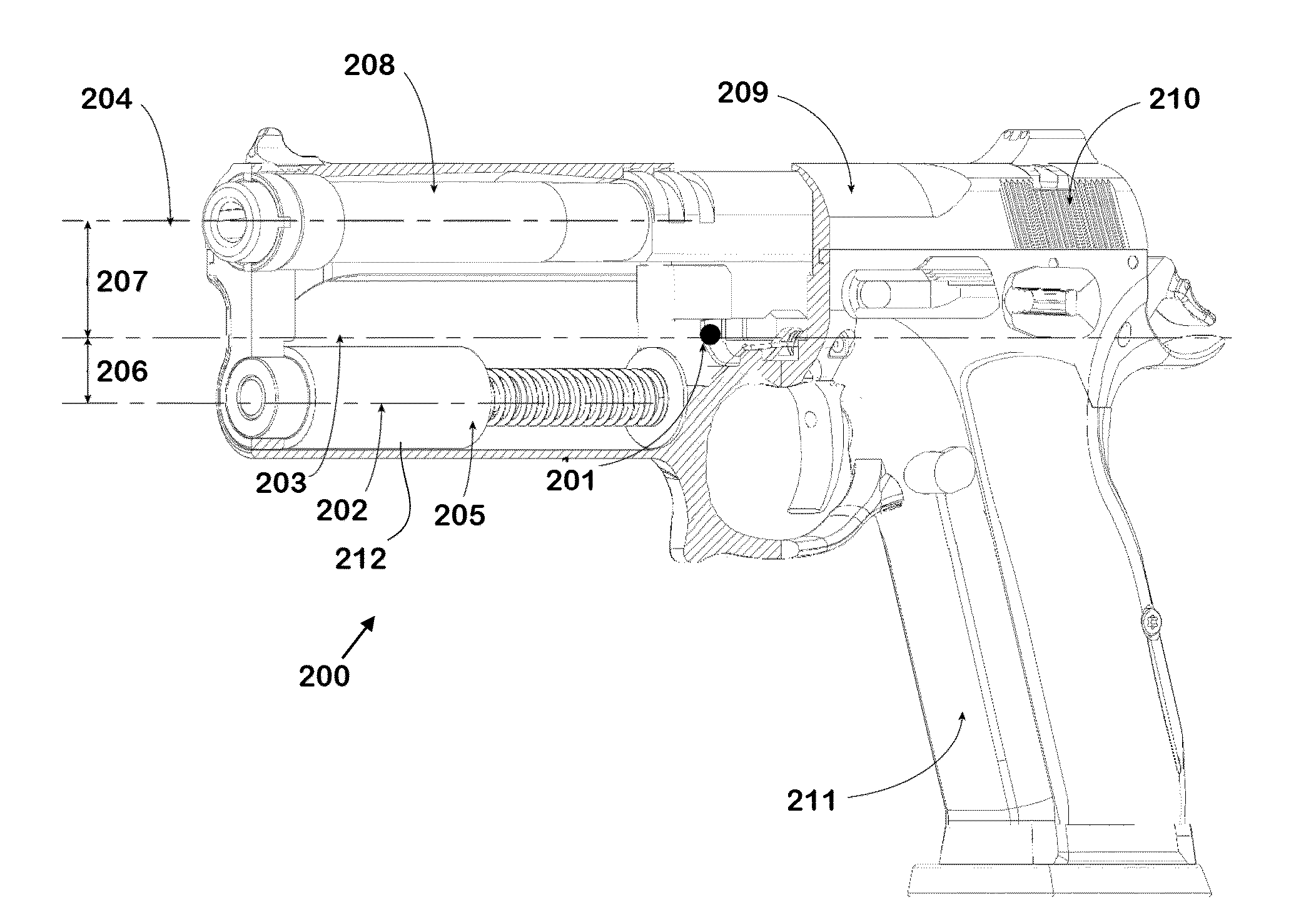
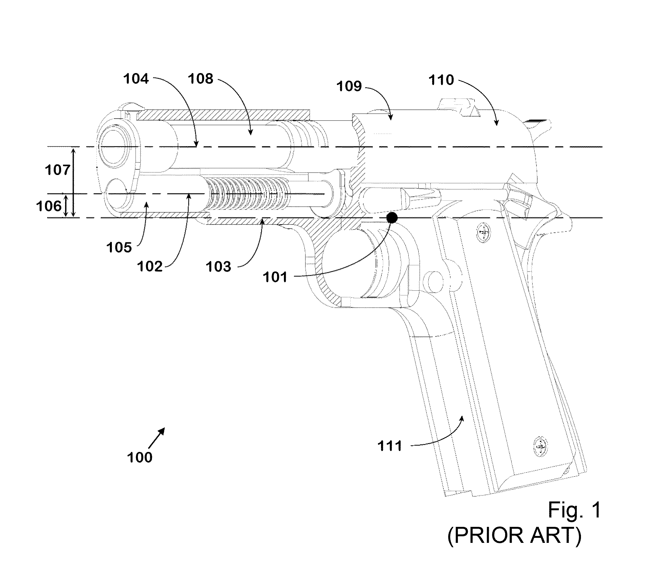
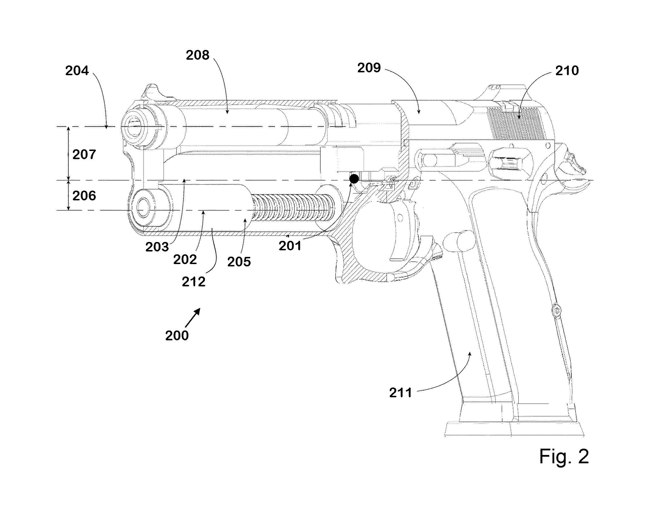
[0015]FIGS. 2 and 4a-4c illustrate a firearm of the Browning type according to the present invention according to an exemplary and non-restrictive embodiment, as compared to corresponding drawings of a firearm of the prior art depicted in FIGS. 1 and 3a-3c. It will be evident to the person skilled in the art to freely combine several or all of the different aspects of the embodiment discussed here and / or described in the claims as will be deemed suitable for a specific implementation of the invention. Throughout this disclosure, terms like “advantageous”, “exemplary” or “preferable” indicate elements or qualities which are particularly suitable (but not essential) to the invention or an embodiment thereof and which may be modified wherever deemed suitable by the skilled person, except where expressly required.

[0016]Referring to FIG. 2, a pistol 200 according to an embodiment of the invention is shown in a perspective view. The center of the mass of the pistol 200 is denoted by a dot...


PUM


Abstract

The present invention relates to firearms, especially to guns, and more particularly to a system for attenuating recoil, reducing muzzle climb and increasing accuracy. The invention provides a recoil attenuating mechanism that is an improvement on the well-known and widely used Browning tilting barrel system which is used mostly in semi-automatic pistols. The recoil attenuation is achieved by redirecting and manipulating the forces of the recoil of the slide of the pistol to a different axis than what is the norm on a regular Browning action, thus reducing muzzle climb substantially in addition to attenuating recoil, and therefore improving accuracy, recovery time, and controllability.

Description

FIELD OF THE INVENTION[0001]The present invention relates to firearms, especially to guns, and more particularly to a system for attenuating recoil, reducing muzzle climb, and increasing accuracy during and after firing (shooting) a bullet.BACKGROUND OF THE INVENTION[0002]The Browning tilting barrel recoil mechanism was invented by J. M. Browning and patented on Apr. 29, 1897, U.S. Pat. No. 580,924 entitled Firearm. Since that time this system has become the most wildly used recoil system in automatic pistols. With various modifications, it is currently used by most of the major pistol makers such as in the Colt 1911, F N browning High Power, Smith and Wesson pistols, Glock, Heckler & Koch, Ruger, C. Z., Tanfoglio and many others. It is a state-of-the-art mechanism (cf. FIGS. 3a-3c), which works by a slide moving backwards and / or recoiling on an axis 32 above the axis 33 of the center of mass 31 of the pistol (see FIG. 3a) while at the same time the barrel tilts upward from the muzz...

Claims


Application Information

Patent Timeline
Patent Type & Authority Applications(United States)
IPC IPC(8): F41A3/86
CPCF41A3/86F41C27/22F41A27/30F41A5/10
Inventor KEDAIRY, FAISAL
Owner SKYCHASE HLDG CORP
Why Eureka
Eureka Blog
Learn More