

Gas laser apparatus
a laser and gas technology, applied in the direction of chemistry apparatus and processes, separation of dispersed particles, separation of separation processes, etc., can solve problems such as lowering resolution
Active Publication Date: 2016-08-25
GIGAPHOTON
View PDF3 Cites 17 Cited by
- Summary
- Abstract
- Description
- Claims
- Application Information
AI Technical Summary
Benefits of technology
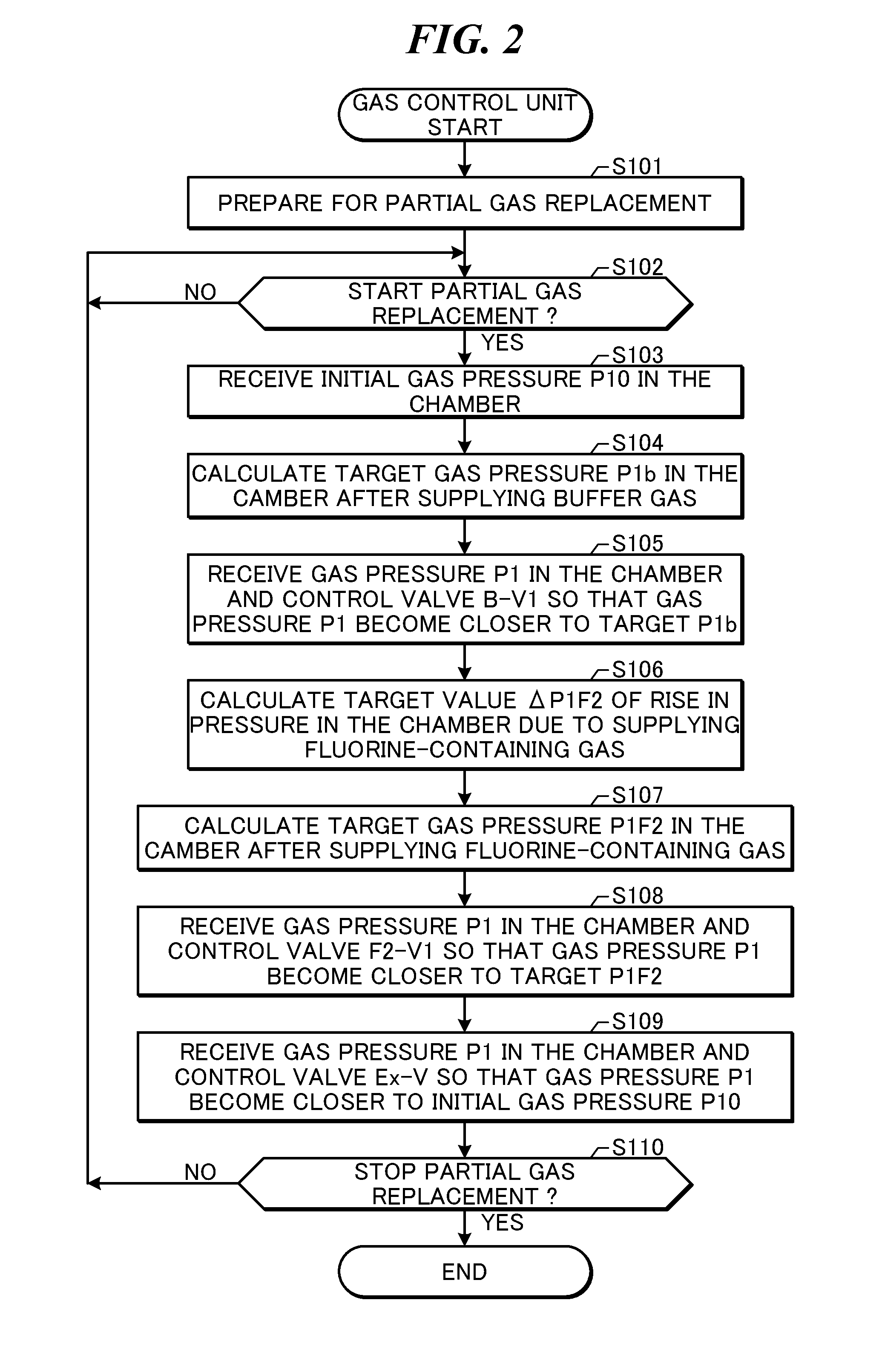
The present patent describes a gas laser apparatus that includes a laser chamber, a purification column, a booster pump, and a controller. The apparatus can supply two different laser gases with different halogen gas concentrations to the laser chamber. The purification column removes halogen gas and a halogen compound from the exhaust gas. The booster pump raises the pressure of the gas that passes through the purification column to a higher pressure than the operating gas pressure of the laser chamber. The controller calculates the amount of gas needed for the laser chamber and controls the valves accordingly. The technical effect of this patent is to provide a gas laser apparatus that can efficiently supply high-quality laser gas to the laser chamber while removing harmful substances from the exhaust gas.
Problems solved by technology
Therefore, the constitution of a projector lens by a material that transmits ultraviolet rays such as KrF or ArF laser light may cause chromatic aberration, thus lowering resolution.
Method used
View moreImage
Smart ImageViewing Examples

Examples
Login to View More PUM
| Property | Measurement | Unit |
|---|---|---|
| Pressure | aaaaa | aaaaa |
| Concentration | aaaaa | aaaaa |
Abstract
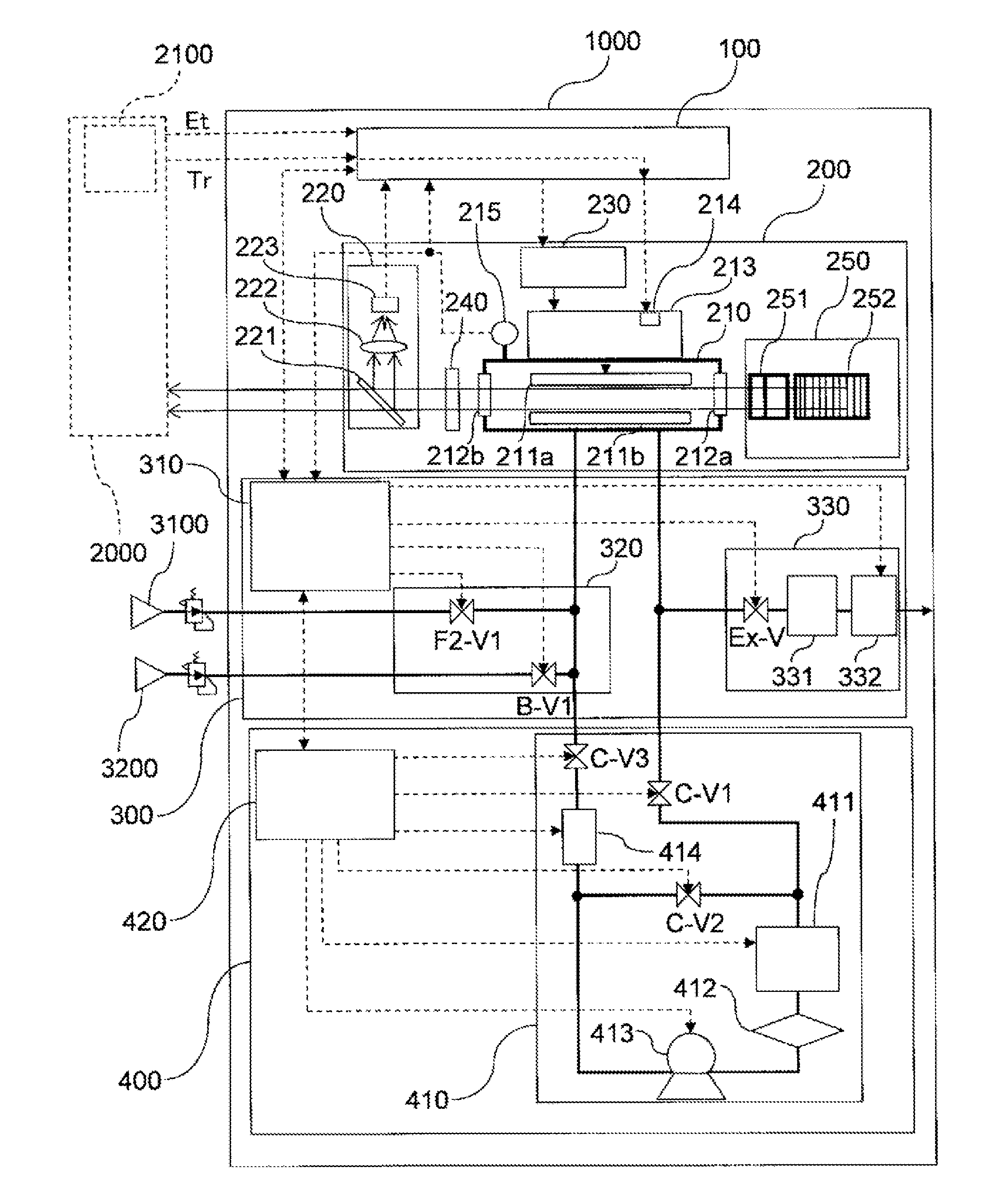
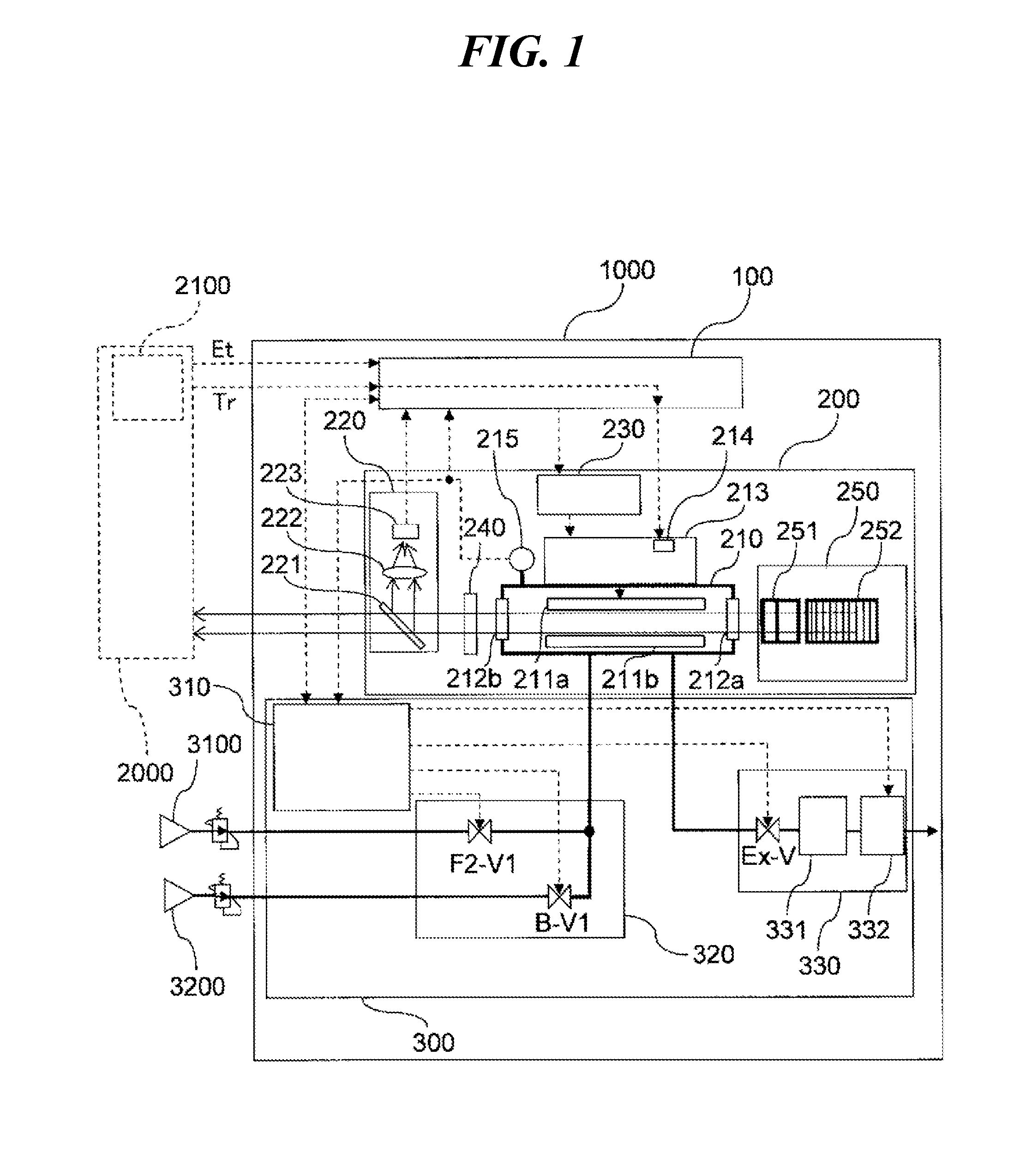
A gas laser apparatus may include: a laser chamber connected through a first control valve to a first laser gas supply source that supplies a first laser gas containing a halogen gas and connected through a second control valve to a second laser gas supply source that supplies a second laser gas having a lower halogen gas concentration than the first laser gas; a purification column that removes at least a part of the halogen gas and a halogen compound from at least a part of a gas exhausted from the laser chamber; a booster pump, connected through a third control valve to the laser chamber, which raises a pressure of a gas having passed through the purification column to a gas pressure that is higher than an operating gas pressure of the laser chamber; and a controller that calculates, on a basis of a first amount of a gas supplied from the booster pump through the third control valve to the laser chamber, a second amount of the first laser gas that is to be supplied to the laser chamber and controls the first control valve on a basis of a result of the calculation of the second amount.
Description
TECHNICAL FIELD[0001]The present disclosure relates to a gas laser apparatus.BACKGROUND ART[0002]In recent years, along with the miniaturization and integration of semiconductor integrated circuits, a semiconductor exposure device (hereinafter referred to as “exposure device”) has been required to have higher resolution. For this reason, shortening of the wavelength of light that is emitted from an exposure light source has been under development. Generally, as an exposure light source, a gas laser apparatus is used instead of a conventional mercury lamp. For example, as a gas laser apparatus for exposure, a KrF excimer laser apparatus configured to output ultraviolet laser light with a wavelength of 248 nm as well as an ArF excimer laser apparatus configured to output ultraviolet laser light with a wavelength of 193 nm may be used.[0003]As next-generation exposure technology, immersion exposure has been put to practical use. In immersion exposure, a gap between an exposure lens in ...
Claims
Login to View More Application Information
Patent Timeline
 IPC IPC(8): H01S3/036H01S3/225B01D53/04H01S3/104
CPCH01S3/104H01S3/225H01S3/036B01D53/346B01D53/82B01D2259/40003B01D2251/602B01D2253/108B01D2257/2027B01D2258/0216B01D53/0446B01D2251/404B01D53/685B01D53/86B01D2255/20753B01D2255/20761H01S3/2366
InventorSUZUKI, NATSUSHIWAKABAYASHI, OSAMUTSUSHIMA, HIROAKIYASHIRO, MASANORI
OwnerGIGAPHOTON