Device for remote oil detection

Active Publication Date: 2016-09-01
OCEAN VISUALS AS
View PDF5 Cites 8 Cited by
  • Summary
  • Abstract
  • Description
  • Claims
  • Application Information

AI Technical Summary

Benefits of technology

[0007]An object of the present invention is to provide a technical solution for remote detection and classification of chemical ...

Problems solved by technology

Thirdly, it should handle harsh environmental conditions, namely high salinit...

Method used


Image

  • Device for remote oil detection
  • Device for remote oil detection
  • Device for remote oil detection

Examples


Embodiment Construction

[0018]To provide device operation at harsh environmental conditions, namely high humidity and salinity, and low temperature, the following technical solutions are used.

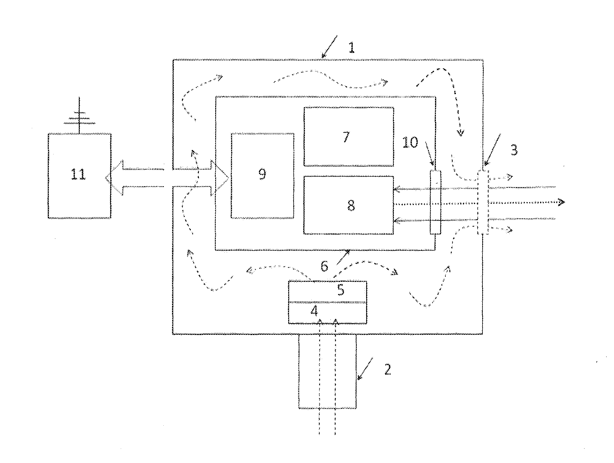
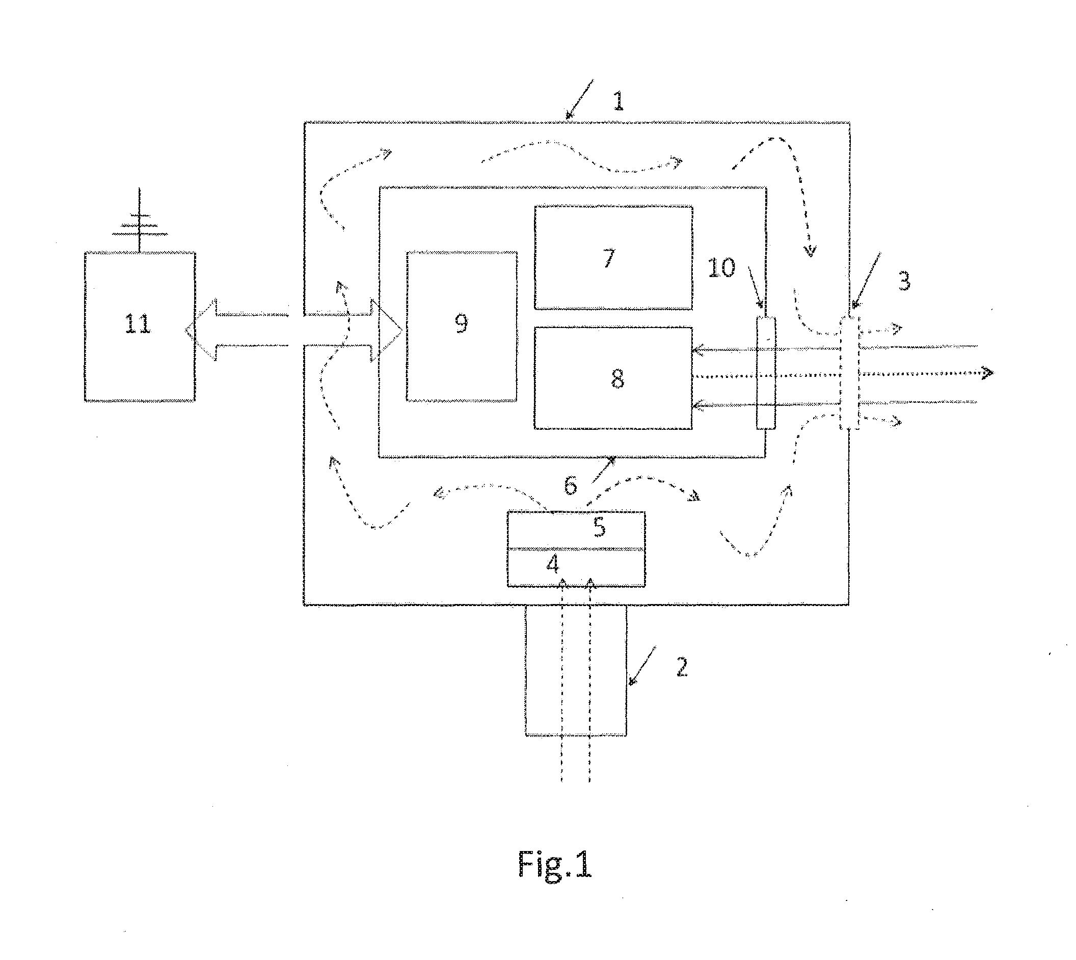
[0019]In the first embodiment (FIG. 1) the LIDAR is designed inside the hermetical internal housing 6 filled with N2 at overpressure. The internal housing is located inside the external one containing ambient air intake 2 and open outlet window 3 with closing cap. The inlet airflow is dried, desalinated and heated with the mist removal system 4. The air flow is arranged with air pump at higher than atmosphere pressure thus providing the air circulation through the external housing 1 with air exhaust through the open outlet window 3. In this way the optical window 9 is kept dry and clean. The laser beam and received fluorescence signal are directed through the internal optical window 10. The heater 5 controlled by temperature sensor keeps the LIDAR in internal housing 6 at the preset temperature for effective operation...


PUM


Abstract

This relates to the field of real-time detection of chemical contamination of water in harsh environmental conditions by using laser remote sensing apparatus for detection of oil or oil products. In-time detection and localization of oil pollution in seawater are the measures to minimize potential damages to the marine and coastal environment. A technical solution for remote detection and classification of chemical pollution in water, to optimize operational parameters, weight, size and power consumption of such device, to make possible continuous unattended operation of such device on board of a moving or stationary platform and to provide data processing and reporting the results through communication channels is described.

Description

FIELD OF THE INVENTION[0001]The invention relates to the field of real-time detection of chemical contamination of natural-, processed and run-off water in harsh environmental conditions by using laser remote sensing apparatus of original design.BACKGROUND OF THE INVENTION[0002]In-time detection, localization and optimal clean-up of oil pollution in seawater are all measures to minimize potential damage to the marine and coastal environment. Among other remote sensing techniques used for oil-in-water detection, the laser remote sensing systems (LIDAR) can be specified as advanced sensor for near-range detection, facilitating direct oil measurement and classification (S. Babichenko. Laser Remote Sensing of the European Marine Environment: LIF technology and Applications. In “Remote Sensing of the European Seas”, Vittorio Barale and Martin Gade (Editors), Springer, 2008, 189-204), [1].[0003]LIF LIDAR is based on the detection and analysis of the spectra of Laser Induced Fluorescence (...

Claims


Application Information

Patent Timeline
IPC IPC(8): G01N21/64G01N33/18G01S17/88G01N21/15
CPCG01N21/6402G01S17/88G01N33/1833G01N21/15
Inventor BABICHENKO, SERGEYVINT, LEINO
Owner OCEAN VISUALS AS
Why Eureka
Try Eureka