Power Conversion Apparatus and Photovoltaic System

a technology of power conversion apparatus and photovoltaic system, which is applied in the direction of dc-ac conversion without reversal, ac network circuit arrangement, semiconductor devices, etc., can solve problems such as damage to solar panels, and achieve the effect of preventing overcurrent of solar panels and sufficient heat quantity

Inactive Publication Date: 2016-09-01
HITACHI LTD
View PDF3 Cites 6 Cited by
  • Summary
  • Abstract
  • Description
  • Claims
  • Application Information

AI Technical Summary

Benefits of technology

[0007]The present invention provides a photovoltaic system, and a power conversion apparatus that are capable of supplying a snow melting current which may supply a sufficient heat quantity to a solar panel while preventing an overcurrent of the solar panel.
[0009]According to the present invention, a photovoltaic system, and the power conversion apparatus that are capable of supplying a snow melting current which may supply a sufficient heat quantity to the solar panel while preventing the overcurrent of the solar panel are provided.

Problems solved by technology

In order to supply the sufficient heat quantity, a current value for determining the snow melting completion is necessarily set to be excessive, and there is a concern to damage the solar panel due to an overcurrent.

Method used


Image

  • Power Conversion Apparatus and Photovoltaic System
  • Power Conversion Apparatus and Photovoltaic System
  • Power Conversion Apparatus and Photovoltaic System

Examples


first embodiment

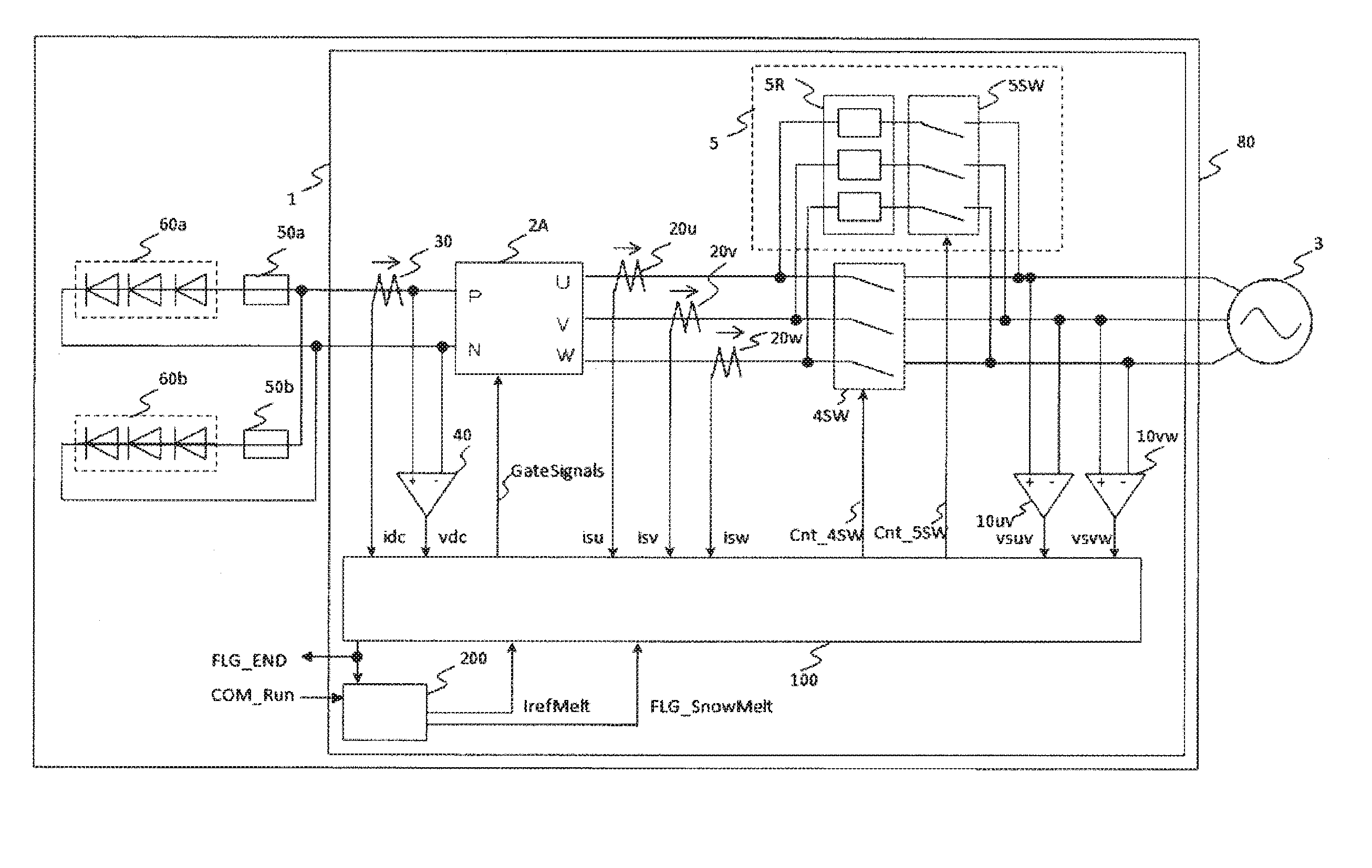
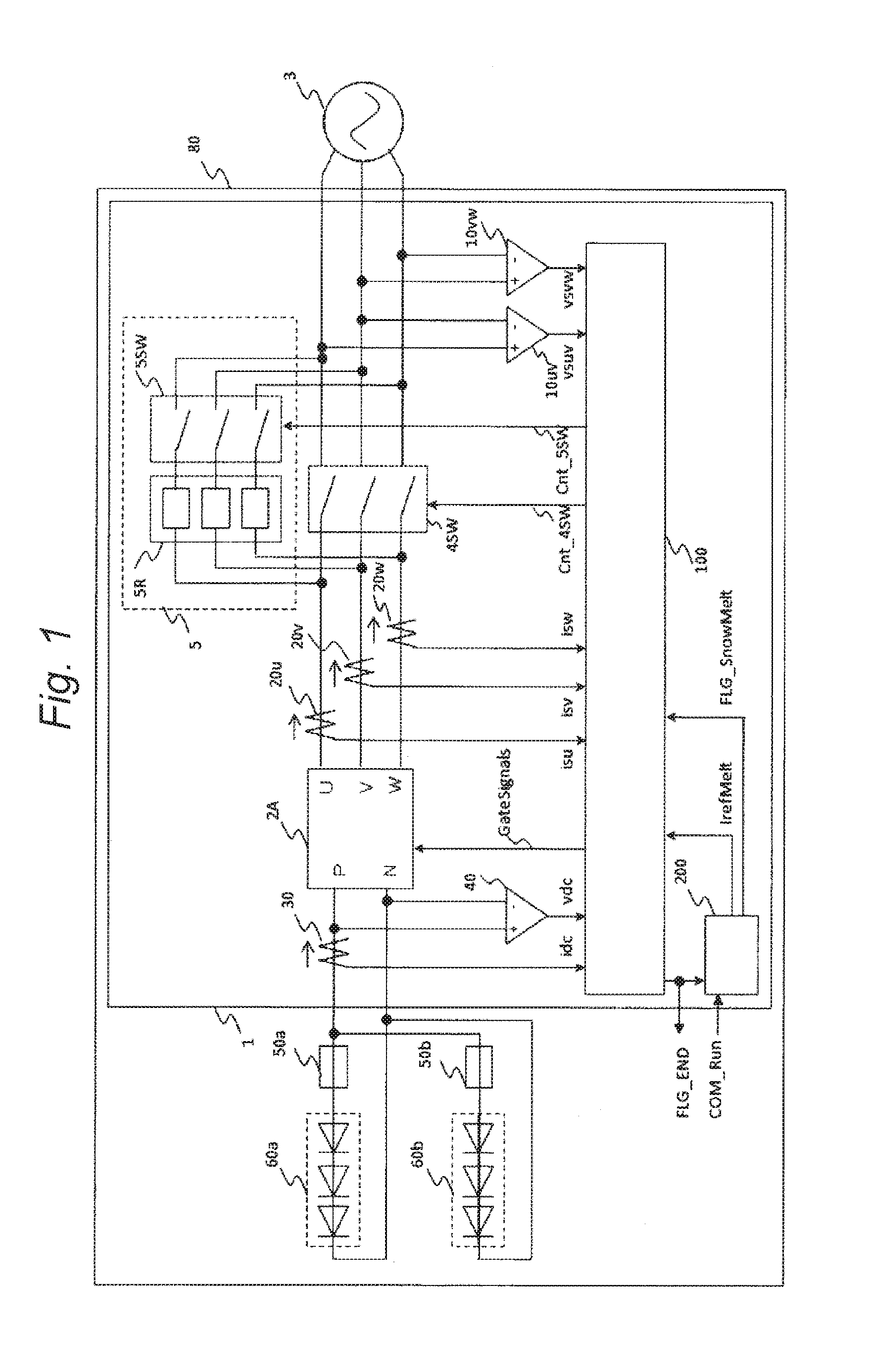
[0025]FIG. 1 is a configuration view of a photovoltaic system in a first embodiment.

[0026]A photovoltaic system 80 according to the first embodiment of the present invention, is configured by strings 60a and 60b where a plurality of solar panels are connected in series, string protection fuses 50a and 50b, and a solar inverter 1. The strings 60a and 60b are connected to a direct current terminal of the solar inverter 1 through the string protection fuses 50a and 50b. Therefore, an alternating current terminal of the solar inverter 1 is connected to a power system 3. The solar inverter 1 has a function of controlling the power which is delivered between the strings 60a and 60b and the power system 3.

[0027]The photovoltaic system 80 of the first embodiment, has two control modes. One is a power generating mode that transmits the power to the power system 3 by converting the direct current power which is obtained from the strings 60a and 60b being the solar panels into the alternating ...

second embodiment

[0096]A second embodiment of the present invention will be described by using FIG. 8. FIG. 8 is an overview of a photovoltaic system in the second embodiment.

[0097]The difference between the second embodiment and the first embodiment of the present invention, is a point in which the photovoltaic system 80 includes an integrated control portion 500, or blocking diode circuits 70a and 70b instead of the fuses 50a and 50b are included in the strings 60a and 60b.

[0098]When a plurality of strings are connected in parallel, there is a case where a blocking diode is included as a purpose of preventing the inflow of a fault current from other strings at the time of generating a short-circuit fault within the string. The embodiment presents the photovoltaic system 80 that may realize the snow melting run even when the above diode is included.

[0099]In the photovoltaic system 80 illustrated in FIG. 8, components which are the same as the photovoltaic system 80 according to the first embodimen...

third embodiment

[0108]A third embodiment of the present invention will be described by using FIG. 10. FIG. 10 is an overview of a photovoltaic system in the third embodiment.

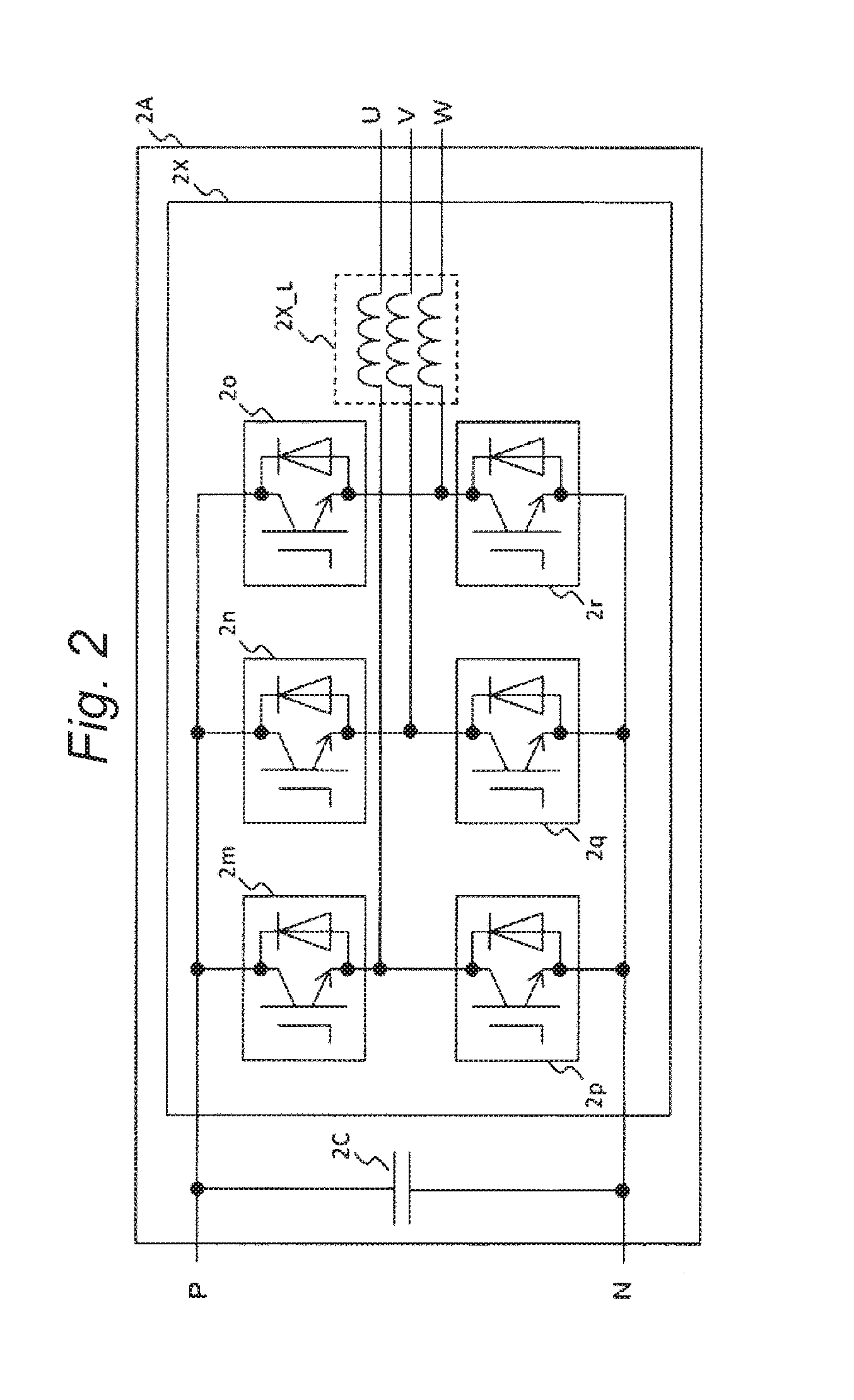
[0109]The difference between the third embodiment and the first embodiment, is a point in which a power conversion portion 2B of the solar inverter 1 is configured by the inverter 2X, and a chopper 2Y.

[0110]The chopper 2Y is capable of adjusting the voltage which is supplied to the strings 60a and 60b at very high speed, by changing a duty ratio of the IGBT module. Moreover, since it is possible to supply the voltage which is lower than the output lower limit value Vdc0 of the inverter 2X to the string, it is possible to widen a selection range of the string.

[0111]Hereinafter, the details thereof are written. Here, the components which are the same as the first embodiment are designated by the same signs, and the overlapped description will be omitted.

[0112]The power conversion portion 2B which is included in the solar inverter...


PUM


Abstract

A power conversion apparatus that is connected between a solar panel and a power system, in which the power conversion apparatus includes a power generating mode that converts a generated power of the solar panel into an alternating current power, and a snow melting mode that heats the solar panel by obtaining the power from the power system, and supplying the power to the solar panel, and at the time of the snow melting mode, the power conversion apparatus controls a voltage which is output to the solar panel such that a first current value being a value where a current that is supplied to the solar panel from the power conversion apparatus is smaller than an overcurrent level of the solar panel flows in a predetermined period.

Description

BACKGROUND OF THE INVENTION[0001]1. Field of the Invention[0002]The present invention relates to a power conversion apparatus and a photovoltaic system.[0003]2. Background Art[0004]In recent years, a photovoltaic system where solar panels and a power system are interconnected through an inverter, has been widely used. Since the solar panel obtains the generated power by solar radiation, a quantity of the generated power is reduced or the power generation is not possible when the solar radiation is blocked. As one of causes which block the solar radiation, there is deep snow that is accumulated on the solar panel. In order to prevent the deep snow, a study that prompts sliding down of the snow by increasing a slope angle of the panel in a deep snow region has been made. However, there is a case where the deep snow or the ice on the panel is not sufficiently slid down in spite of the above study, and the quantity of the generated power from the photovoltaic system is reduced due to th...

Claims


Application Information

Patent Timeline
Patent Type & Authority Applications(United States)
IPC IPC(8): H02S40/12H02S40/44H02S40/32
CPCH02S40/12H02S40/44H02S40/32H01L31/02021H02M7/48H02J2300/24H02J3/381Y02E10/56
Inventor ITO, TOMOMICHIKUNISADA, HIDEAKISONOBE, KAORUNISHIZAWA, HIROTAKANAKAJIMA, YOSHIROWADA, TAMAKI
Owner HITACHI LTD
Why Eureka
Try Eureka