Ice making system

A technology of ice maker and branch pipeline, which is applied in the direction of ice making, ice making, refrigerator, etc. It can solve the problems of affecting deicing, insufficient heating, and increased power consumption, so as to improve the utilization rate of electric energy and increase the production capacity. Ice time, the effect of reducing the occupied area

Active Publication Date: 2010-09-29
广州冰泉制冷设备有限责任公司
View PDF0 Cites 0 Cited by
  • Summary
  • Abstract
  • Description
  • Claims
  • Application Information

AI Technical Summary

Problems solved by technology

[0002] For the current general-purpose ice machines, especially edible ice machines, there is no edible ice machine that can achieve large-scale production. At present, the largest daily production capacity is less than 1500 kg, which is mainly limited by the refrigeration technology. The main reason is It is impossible to realize automatic deicing
If recycling can be achieved, only 1 ton of circulating cooling water is needed to meet the technological requirements of the refrigeration system for the daily production of 810 kg of ice cubes, and the cooling water consumption rate is less than 3%.
[0004] From the above, when deicing is performed, the refrigerant only flows through the ice maker and compressor through the heat supply valve 14. Practice has proved that as the deicing continues, this cycle causes the temperature of the refrigerant to enter the compressor to increase after being compressed. The lower and lower, when it lasts for a certain period of time, the temperature of the refrigerant gas discharged from the compressor is very low, and even cannot reach the temperature required for deicing, which will easily cause insufficient heating, affect deicing, and make the deicing time very long. It takes 2 minutes to 3.5 minutes, which directly leads to increased power consumption
De-icing cannot be achieved if the ice maker is large, or if the ice cubes are thick
[0005] At the same time, this system can only meet the deicing requirements of two 450kg / 24-hour ice makers. If the number of ice makers increases or the specifications increase, normal deicing will not be achieved.
Therefore, this system limits the development of the ice machine to the direction of large-scale energy saving and water saving
[0006] In addition, the system has an obvious design error that does not meet the refrigeration technical specifications, that is, the high-temperature and high-pressure gas discharged from the compressor enters the ice maker through the heating valve to exchange heat with ice cubes, and becomes a gas-liquid mixture and enters the compressor.
When the liquid gradually accumulates inside the compressor, it is easy to cause liquid shock of the compressor, which is absolutely not allowed in refrigeration technical specifications, which will cause damage to the compressor

Method used


Image

  • Ice making system
  • Ice making system
  • Ice making system

Examples


Embodiment 1

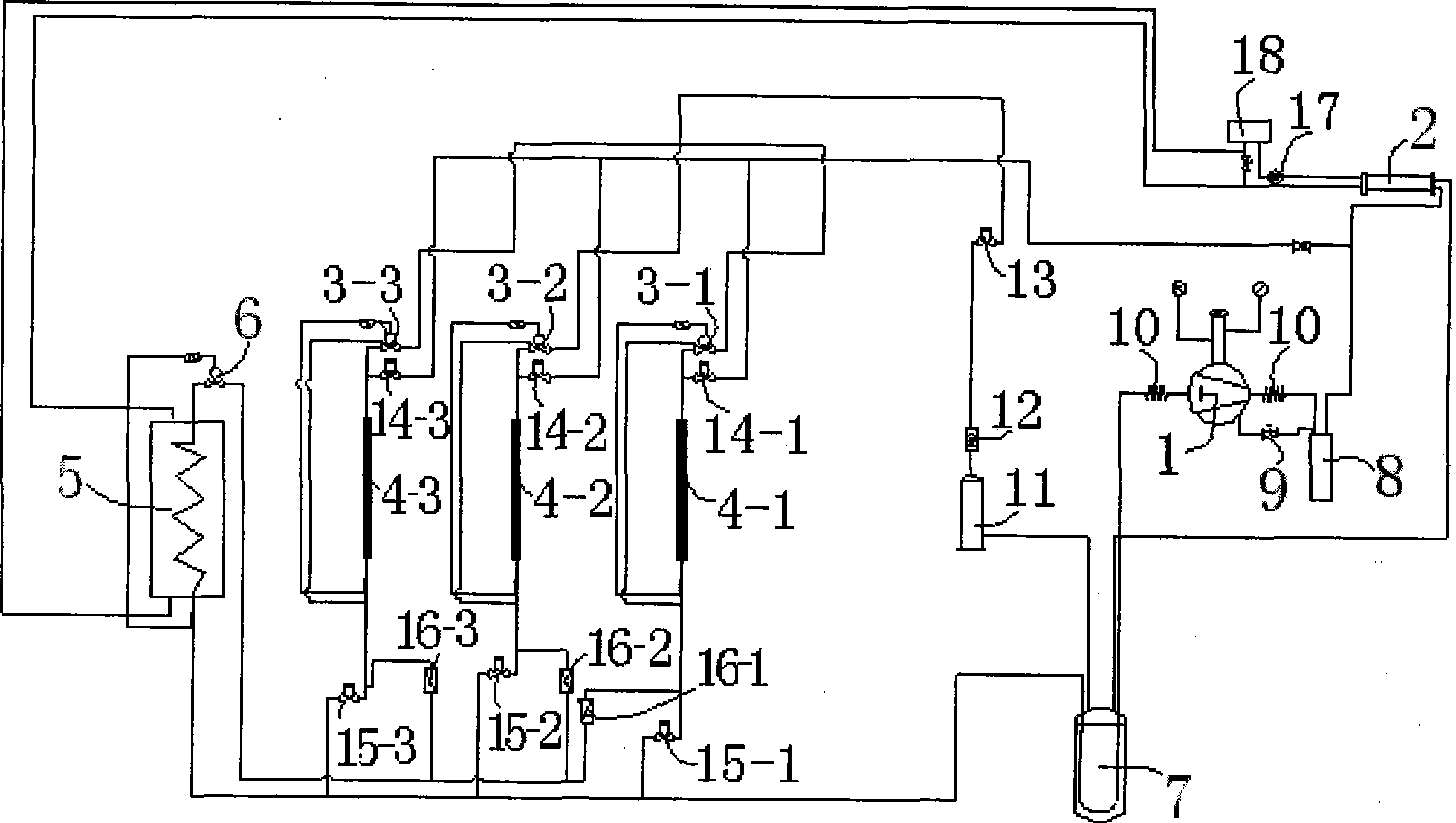
[0035] Such as figure 2 As shown, the ice maker group 4 can be provided with three groups. The pipeline from the condenser 2 passes through the gas-liquid separator 7 and is connected to the filter 11 and the sight glass 12 , and then connected to the liquid supply valve 13 . The pipeline behind the liquid supply valve 13 is provided with three branch pipelines, which respectively pass through the throttling mechanism 3-1, the throttling mechanism 3-2 and the throttling mechanism 3-3 and the corresponding ice maker group 4-1 to make ice The ice maker group 4-2 is connected with the ice maker group 4-3, and the pipeline from the ice maker group of each group is provided with two branch pipelines, and one branch pipeline passes through the air return valve 15-1 and the air return valve respectively. 15-2 and the air return valve 15-2 converge in one main pipeline, and then connect to the compressor 1 after passing through the gas-liquid separator 7, and the other branch pipelin...

Embodiment 2

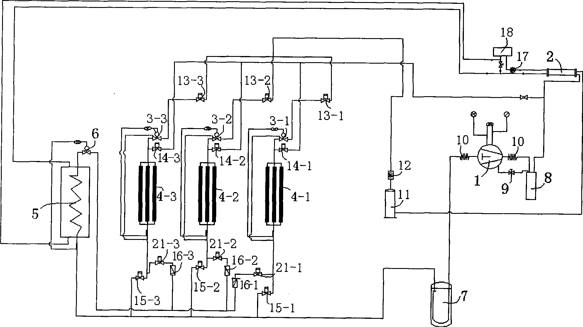
[0038] Such as image 3 As shown, there are three groups of ice maker groups, which are ice maker group 4-1, ice maker group 4-2 and ice maker group 4-3, and each ice maker group can be equipped with three ice makers , the pipeline from the condenser 2 can be provided with three branch pipelines after the gas-liquid separator 7, the filter 11 and the sight glass 12, respectively connected to the liquid supply valve 13-1, the liquid supply valve 13-2 and the liquid supply valve. The valve 13-3 is connected to the corresponding ice maker group 4-1, ice maker group 4-2 and ice making unit respectively through the throttling mechanism 3-1, throttling mechanism 3-2 and throttling mechanism 3-3. The pipelines from each ice maker group are connected with two branch pipelines, and one branch pipeline passes through the air return valve 15-1, the air return valve 15-2 and the air return valve 15- 3 are gathered in one main pipeline, and then connected to the compressor 1 after passing...

Embodiment 3

[0041] Such as Figure 2~3 As shown, the heat exchange medium pipeline of the bypass heat exchanger 5 is connected with the cooling tower 18, the cooling tower 18 is connected with the pipeline of the condenser 2, and the pipeline of the condenser 2 is connected with the bypass heat exchanger 5; the bypass heat exchanger 5. The condenser 2 and the cooling tower 18 form a cooling water recycling system. A cooling water pump 17 is arranged on the pipeline between the cooling tower 18 and the condenser 2 . Under the action of the cooling water pump 17, the cooling water enters the condenser 2 to exchange heat with the high-temperature and high-pressure gaseous refrigerant, changing the refrigerant from a gaseous state to a liquid state. Outflow is divided into two paths, one path flows through the bypass heat exchanger, and heat exchange is performed with the refrigerant in the bypass heat exchanger, heat is released, and the temperature is lowered, and flows back to the cooling...


PUM


Abstract

An ice-making system includes compressor, condenser, throttling mechanism, ice-making device set, bypath heat exchanger, liquid supply valve, heat supply valve, air return valve and one-way valve. The compressor output pipeline divides into two branch pipelines, one branch is connected with the liquid supply valve via the condenser, and then is connected with the ice-maker set via the throttling mechanism; the other branch is connected with the ice making device via the heat supply valve; there are at least two group ice making device set. The pipeline from the ice making device set divides into two branches, one branch is connected with the air return valve, and then converged to a main pipeline and is connected with the compressor; the other branch is connected with the one-way valve, and then converged to a main bypath pipeline, and is connected with the bypath heat exchanger, then is connected with the compressor.

Description

technical field [0001] The invention relates to the technical field of refrigeration, in particular to an ice-making system that utilizes the exhaust heat of a compressor of the system itself for deicing. Background technique [0002] For the current general-purpose ice machines, especially edible ice machines, there is no edible ice machine that can achieve large-scale production. At present, the largest daily production capacity is less than 1500 kg, which is mainly limited by the refrigeration technology. The main reason is The problem is that automatic de-icing cannot be achieved. In addition, small ice machines have high energy consumption, and the cooling water often cannot be recycled, resulting in a serious waste of cooling water resources. Taking an edible ice machine with a daily output of 810 kg as an example, as much as 10 tons of water is used for cooling a day, and the water is often only used for one cooling and is directly discharged as waste water, and the ...

Claims


Application Information

Patent Timeline
Patent Type & Authority Patents(China)
IPC IPC(8): F25C1/00F25B5/02
Inventor 冯昊艳杨春林张绍志
Owner 广州冰泉制冷设备有限责任公司
Why Eureka
Try Eureka