Catheter and method to localize ectopic and reentrant activity in the heart

a technology of ectopic and reentrant activity and catheter, which is applied in the field of catheter, can solve the problems of destroying vast portions of the atria, limiting the success rate of pulmonary vein isolation in patients with persistent af, and affecting the detection of ectopies. , to achieve the effect of facilitating the detection of ectopies

Pending Publication Date: 2016-09-15
RGT UNIV OF MICHIGAN
View PDF11 Cites 23 Cited by
  • Summary
  • Abstract
  • Description
  • Claims
  • Application Information

AI Technical Summary

Benefits of technology

[0016]More specifically, the initial spreading site of the activity on any closed, but not electrically insulating, intra-cavitary surface is geometrically connected to the initial spreading site on the heart wall (i.e., ectopy) and is used as a remote guidance toward that ectopy. In addition, during reentrant activity in the cardiac walls, a filament, defined by the pivoting axis line of transmembrane or extracellular potentials, is extended into the volume conductor medium surrounding the muscle and is only interrupted at a non-conducting boundary. The filament in the heart cavity is thus also geometrically connected to rotors in the heart wall and is used as a remote guidance for the rotor. To facilitate the detection of the ectopies and filament in the cavity, a catheter probe assembly has been developed using what is called herein a “geodesic resistance” to detect these patterns and guide the catheter toward these patterns (i.e., reentrant and ectopic patterns of electrical activation spread) on the heart walls.

Problems solved by technology

Nonetheless, complex cardiac arrhythmias, such as atrial fibrillation (AF), atrial tachycardia (AT), and sustained ventricular tachycardia (VT) still present significant understanding and treatment challenges, especially given that anti-arrhythmic medications do not effectively control all the symptoms associated with these rhythm disorders.
Paroxysmal AF is commonly treated with ablation that isolates pulmonary veins, but success rates of pulmonary veins isolation in patients with persistent AF is limited as electrical isolation of pulmonary vein foci is frequently insufficient.
Additional linear ablation and / or ablation targeting complex fractionated atrial electrograms (CFAEs) are then often employed, which frequently result in the destruction of vast portions of the atria.
The contact mapping systems are more acceptable than the non-contact systems for diagnostic of arrhythmias, but none of the electroanatomic mapping system currently used in the clinic has been fully validated for mapping reentrant and ectopic activity during fibrillation
Rotors emit 2D spiral waves and 3D scroll waves that propagate through the heterogeneous cardiac muscle and interact with anatomic and functional obstacles, leading to wave front fragmentation and fibrillatory conduction.
This result agrees well with the relatively poor success rate of ablation in the pulmonary vein region in such patients.
One of the major limitations of currently available ablation techniques is the difficulty of determining and visualizing electrical activity with sufficient sensitivity and specificity to accurately determine the location of potential sources of arrhythmia.
Although the high-resolution method of optical imaging of electrical impulses can identify high frequency sources, it has not yet been developed for clinical use in patients.

Method used


Image

  • Catheter and method to localize ectopic and reentrant activity in the heart
  • Catheter and method to localize ectopic and reentrant activity in the heart
  • Catheter and method to localize ectopic and reentrant activity in the heart

Examples


example 1

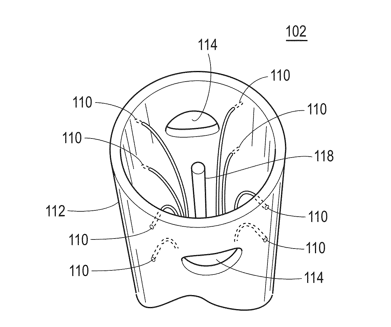
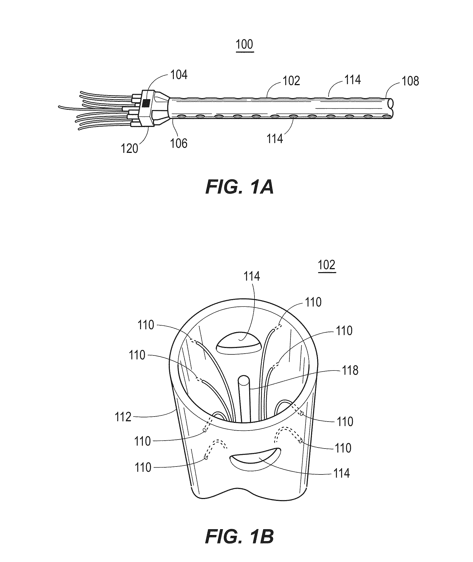
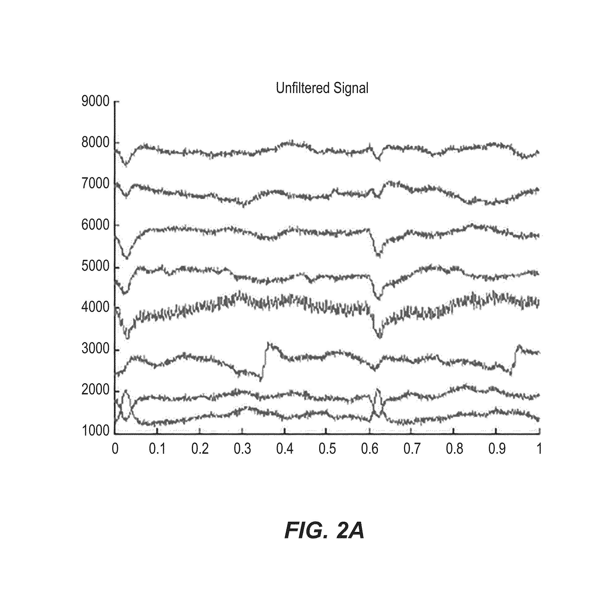
[0056]In an example implementation, a catheter, e.g., catheter 102, was inserted into a solution-filled cavity of the left atrium (LA; no contact with the walls) of a sheep experience atrial fibrillation (AF). Electrical signal data was collected and recorded, specifically voltage time series data, at each of the 8 outer electrodes functioning as unipolar electrodes. A common reference signal was constructed from joining 4 (or 3; depending on availability), of opposing electrodes, i.e., vortices, through a high resistance connection (i.e., a local Wilson central terminal configuration). FIG. 2A shows sample data collected in the 8 vortices electrodes during AF in the sheep with a central HCP electrode maintained at a 0V difference with the grounded heart, i.e., short circuited with the heart. In the example shown in FIG. 2B, filtering is done on the electrical signal data, by a processing device. For example, the original data was passed through a bandpass filter and filtered at 1-2...

example 2

[0062]In an example implementation of a catheter like that of catheter 300, cardiac extracellular electrical activity was recorded at 8 electrodes, for 8 vertices of a cube. In this example, the edge length of that cube was 1 cm. The spacing distance is determined from the size of the catheter. As with the catheter 102, the catheter 300 the space between the vertices electrodes is empty and free to contain the volume conductor.

[0063]In an example implementation, data was acquired from by inserting the catheter into a solution-filled cavity of the left atrium (“LA”; no contact with the walls) of a sheep during pacing sinus rhythm and atrial fibrillation, similar to that of Example 1 above. Voltage time series were recorded at each of the 8 electrodes 302 as unipolars with a common reference signal constructed from joining 4 (or 3; depending on availability), of opposing vortices through a high resistance connection, e.g., like a Wilson terminal. FIG. 7 shows sample data collected dur...


PUM


Abstract

Techniques are provided that identify and localize on to reentrant and ectopic patterns of electrical activation in the heart wall. These patterns may correspond to atrial fibrillation, ventricular fibrillation, or other heart arrhythmia conditions. The techniques detect these patterns of electrical activity using a multi-lead an intra-cavitary catheter that, along with a controller, is able to track, over a multi-dimensional cubic space, reentrant activity and identify filaments in the heart cavity. The intra-cavitary catheter includes multiple conducting poles positioned in a configuration relative to each other and functioning as either or both sensing and active poles for measuring electrical pathways in the heart wall and over the multi-dimensional space.

Description

CROSS-REFERENCE TO RELATED APPLICATIONS[0001]This application claims the benefit of U.S. Provisional Application Ser. No. 62 / 132,218, filed Mar. 12, 2015, entitled “A Catheter and Method to Localize Ectopic and Reentrant Activity in the Heart,” the entirety of which is hereby incorporated herein by reference.STATEMENT OF GOVERNMENT SUPPORT[0002]This invention was made with government support under HL118304 awarded by the National Institutes of Health. The government has certain rights in the invention.FIELD OF THE INVENTION[0003]The present disclosure relates generally to identifying the heart arrhythmia in a subject and, more particularly, to developing ectopic and reentrant pattern mapping of the subject's heart rhythm using a catheter device.BACKGROUND[0004]The background description provided herein is for the purpose of generally presenting the context of the disclosure. Work of the presently named inventor, to the extent it is described in this background section, as well as as...

Claims


Application Information

Patent Timeline
Patent Type & Authority Applications(United States)
IPC IPC(8): A61B5/042A61B5/0432A61B5/0468A61B5/04A61B5/00A61B5/044A61B5/364
CPCA61B5/0422A61B5/6852A61B5/044A61B2562/0214A61B5/04017A61B5/0432A61B5/0468A61B5/316A61B5/287A61B5/339A61B5/361A61B5/364
Inventor BERENFELD, OMER
Owner RGT UNIV OF MICHIGAN
Why Eureka
Try Eureka