Circuit device, electronic apparatus, and moving object

a circuit device and electronic equipment technology, applied in pulse manipulation, pulse technique, instruments, etc., can solve the problems of insufficient output of multiplexers, inability to achieve the level of multiplexers, and inability to accurately produce a/d-convert values

Inactive Publication Date: 2016-09-15
SEIKO EPSON CORP
View PDF4 Cites 9 Cited by
  • Summary
  • Abstract
  • Description
  • Claims
  • Application Information

AI Technical Summary

Benefits of technology

[0007]An advantage of some aspects of the invention is to provide a circuit device, an electronic apparatus, and a moving object capable of producing an accurate A / D-converted value even when a circuit in a stage upstream of a multiplexer has poor driving capability.

Problems solved by technology

When a circuit in a stage upstream of the multiplexer has poor driving capability, however, the output of the multiplexer is not sufficiently driven when the input signal is selected.
The output of the multiplexer therefore does not reach the level of the input signal by the time when the A / D conversion sampling is performed, and an accurate A / D-converted value is undesirably produced.
As a result, even when the stage upstream of the multiplexer has poor driving capability, the buffer circuit buffers the i-th input signal, whereby an accurate A / D-converted value can be produced.
When the stage upstream of the multiplexer has poor driving capability, the output from the multiplexer ((i−1)-th input signal) undesirably affects and changes the i-th input signal to the multiplexer.
When the cutoff frequency of the passive low-pass filter is lower than the frequency of the time division operation performed by the multiplexer, a state in which the stage upstream of the multiplexer has poor driving capability occurs, and an accurate A / D-converted value cannot be produced.
If an active low-pass filter is used, noise produced by the active low-pass filter is undesirably inputted to the A / D conversion circuit.

Method used


Image

  • Circuit device, electronic apparatus, and moving object
  • Circuit device, electronic apparatus, and moving object
  • Circuit device, electronic apparatus, and moving object

Examples


Embodiment Construction

[0049]Preferable embodiments of the invention will be described below in detail. It is not intended that the embodiments described below unduly limit the contents of the invention set forth in the appended claims, and all configurations described in the embodiments are not necessarily essential as solutions provided by the invention.

1. First Configuration Example

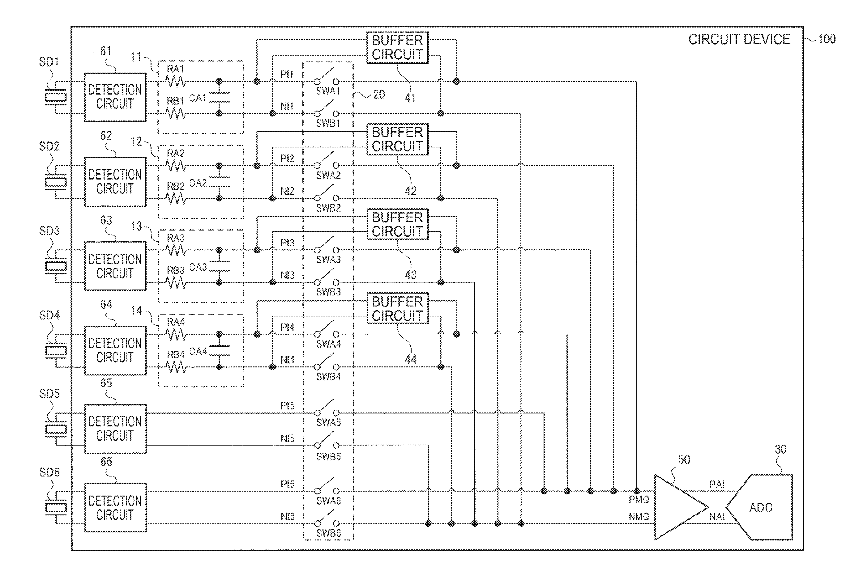
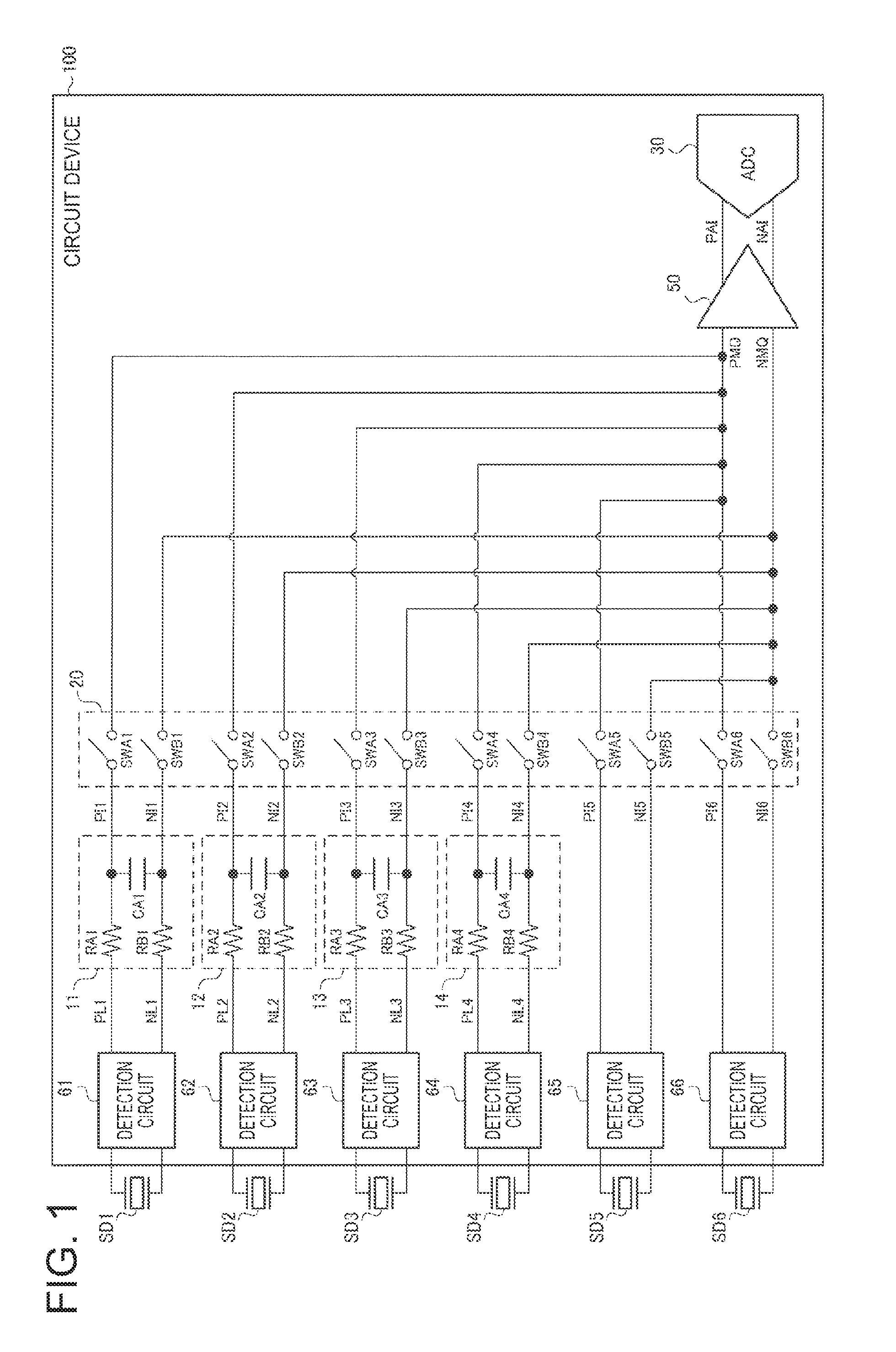
[0050]FIG. 1 shows a first configuration example of a sensor and a circuit device. The sensor of the first configuration example includes physical quantity transducers SD1 to SD6 (first to n-th physical quantity transducers, where n is an integer greater than or equal to 2) and a circuit device (detection device) that receives detection signals from the physical quantity transducers SD1 to SD6 and detects desired signals.

[0051]The circuit device of the first configuration example includes detection circuits 61 to 66 (first to n-th detection circuits), which perform analog front end processing on the detection signals from th...


PUM


Abstract

A circuit device includes a multiplexer that selects an input signal from first to n-th input signals in a time division manner and outputs the selected input signal to an output node, an A/D conversion circuit that receives the first to n-th input signals outputted from the multiplexer to the output node in a time division manner and A/D-converts the received first to n-th input signals in a time division manner, and a buffer circuit provided between an i-th input node and the output node of the multiplexer. The buffer circuit buffers the i-th input signal and outputs the buffered signal to the output node of the multiplexer in a first period. The multiplexer selects the i-th input signal and outputs the selected signal to the output node in a second period. End timing of the second period comes after end timing of the first period.

Description

BACKGROUND[0001]1. Technical Field[0002]The present invention relates to a circuit device, an electronic apparatus, a moving object, and the like.[0003]2. Related Art[0004]In recent years, a gyro sensor, an acceleration sensor, and other motion sensors have come into the spotlight. Use of such a motion sensor, for example, achieves hand-shake blur correction in a camera and intuitive operation input in a game console. An example of related art technology for an apparatus that receives a detection signal from such a sensor device and performs A / D conversion and filtering is a technology disclosed in JP-A-2012-42261. In JP-A-2012-42261, detection signals from sensor devices are A / D-converted in a time division manner, and a multiplexer selects a detection signal to be inputted to an A / D conversion circuit from the detection signals in a time division manner.[0005]When the multiplexer selects an input signal from a plurality of input signals in a time division manner, an input to the A...

Claims


Application Information

Patent Timeline
Patent Type & Authority Applications(United States)
IPC IPC(8): H03K5/15G01P15/09G01P15/125H03K17/00G01C19/5705
CPCH03K5/15013H03K17/005G01P15/09G01P15/125G01C19/5705H03M1/123G01C19/5776G01P15/0897H03M1/468
Inventor UEHARA, JUNAOYAMA, TAKASHI
Owner SEIKO EPSON CORP
Why Eureka
Try Eureka