Method and system for providing pulsed power and data on a bus

a bus and pulsed power technology, applied in the field of methods and systems for providing pulsed power and data on the bus, can solve the problems of system bulky and expensive, prohibitively expensive for some applications, and requires extra board space, so as to avoid collision of messages on the back channel and improve data ra

Active Publication Date: 2016-09-15
VLAAMSE INSTELLING VOOR TECHNOLOGISCH ONDERZOEK NV VITO
View PDF60 Cites 29 Cited by
  • Summary
  • Abstract
  • Description
  • Claims
  • Application Information

AI Technical Summary

Benefits of technology

[0019]One of the main advantages of embodiments of the present invention is that the present system can be built by means of very simple hardware for transmitting data (by the main control unit) and receiving the data (by the slave), as opposed to the prior art circuits, which either don't provide galvanic separation, or require more complicated hardware, such as e.g. described in FR2612019(A1), where the master unit and each slave require a transformer, which is heavier, and more bulky and more expensive than a capacitor. Cost is a very important factor in systems where a plurality of slave units are required, such as e.g. in a rechargeable battery system with multiple balancing units.
[0062]By using an appropriate protocol, collision of messages on the back-channel can be avoided. Several protocols are possible, e.g. a protocol where the master first sends a message or command to one particular slave, where after that one slave is given time to respond on the second bus. When the first slave has sent its data, the master addresses the next slave, etc. But other protocols can also be used.

Problems solved by technology

A disadvantage of such a system is that it requires a modem at each transmitter and receiver side, which makes this system prohibitively expensive for some applications, and requires extra board space (as compared to systems not requiring a modem).
Another disadvantage is that the devices connected to the bus are galvanically coupled to the bus, unless a transformer is used, which again makes the slave units, and thus the system bulky and expensive.
A disadvantage of such a system is that each unit requires a first transformer for receiving power, and an isolating transformer with a ferrite core for the data-communication.
That makes the units, and thus the system bulky, heavy and expensive.
As the slaves 15 are at different potentials, they cannot be connected directly to the CAN-bus, but e.g. may be connected thereto by means of interface devices using opto-coupling, which requires board space and increases the component cost.

Method used


Image

  • Method and system for providing pulsed power and data on a bus
  • Method and system for providing pulsed power and data on a bus
  • Method and system for providing pulsed power and data on a bus

Examples


first embodiment

[0097]FIG. 3 to FIG. 7 will be used to explain the main principles of an embodiment of the present invention.

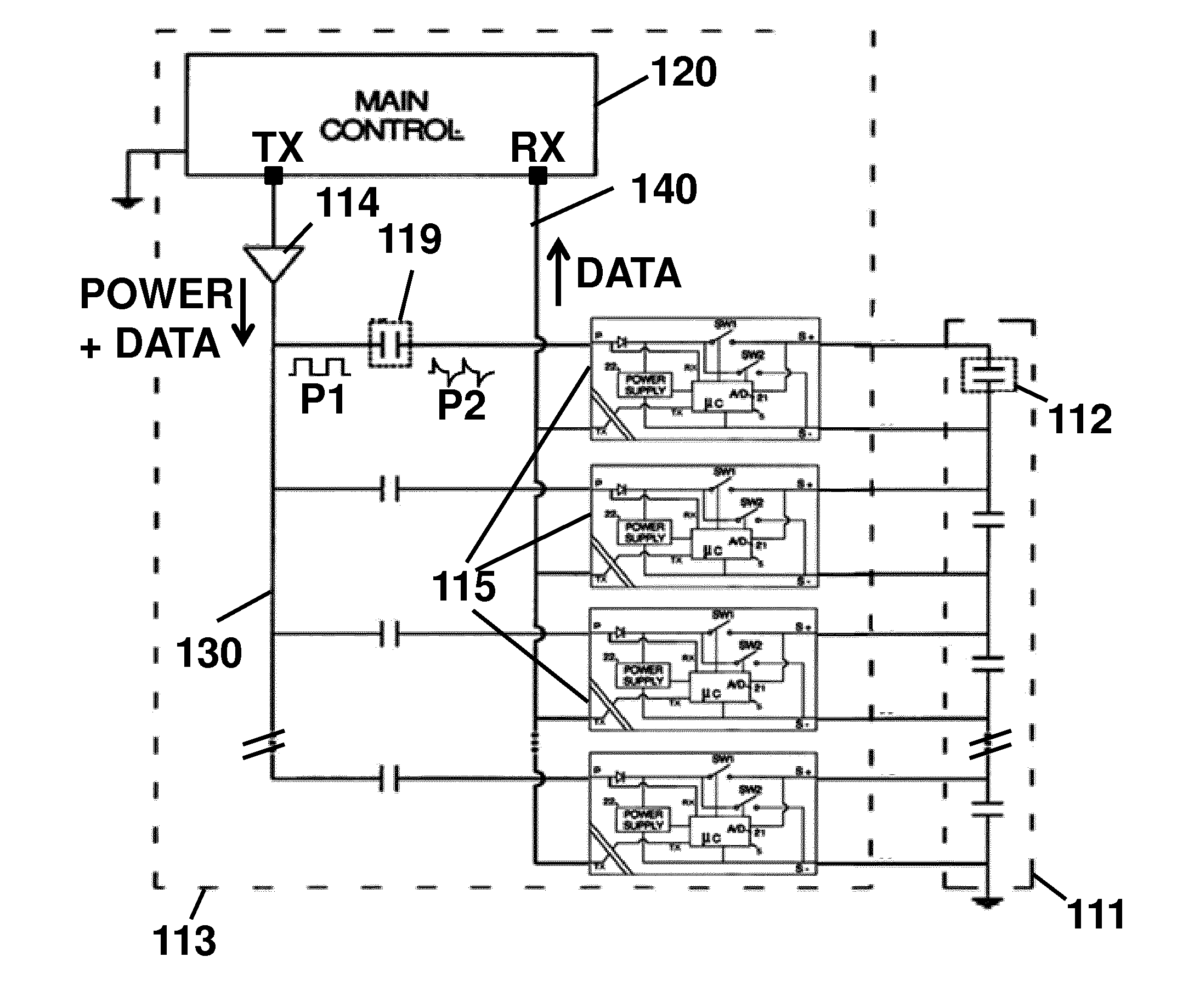
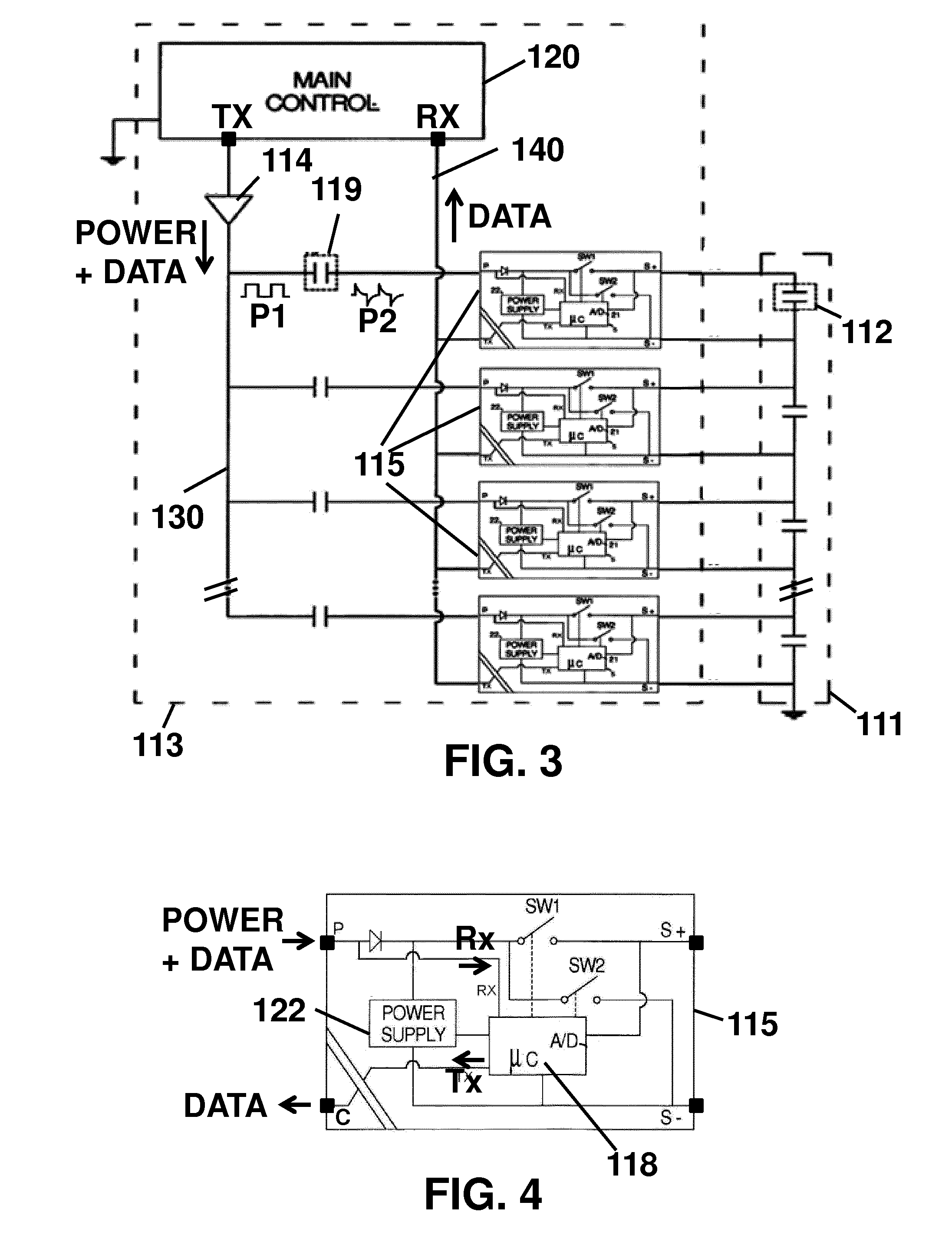
[0098]FIG. 3 shows a system 113 according to aspects of the present invention. The system 113 is a variant of the energy storage system 13 of FIG. 1, but this is not intended to limit the invention to energy storage systems. When comparing the block-diagram of FIG. 3 with that of FIG. 1, it becomes immediately clear that the main difference between both systems 113, 13 is that the data from the main control unit 120 to the one or more slave units 115 occurs over the first bus 130 instead of over the second bus 140, as indicated by the arrows “power and data” and “data”. While not directly evident from FIG. 3, this offers the important advantage that the second bus 140 can now be uni-directional instead of bi-directional. When using opto-couplers, this means that one of the two opto-couplers (one for each direction) can be omitted per slave 115. This is a major advantage in te...

second embodiment

[0126]Having explained the main principles of the present invention by means of the first embodiment described in relation to FIG. 3 to FIG. 7I, further embodiments of the present invention will be easily understood. In the following all the disclosure relating to the First Embodiment above is included here by reference in this embodiment. In particular all pulse wave forms, modulation and demodulation techniques described with reference to FIG. 7a to FIG. 7h are included by reference in this embodiment.

[0127]FIG. 8 shows a second embodiment of a system 213 according to aspects of the present invention, whereby the main control unit 220 is adapted for sending combined power and data pulses over a bus 230 to one or more slaves 215, which slaves 215 are connected to the bus 230 by means of series capacitors 219 (or capacitive circuits, or capacitive devices). The slaves 215 can receive the data in any of the ways or in the same way as described above (first embodiment), e.g. by measur...

third embodiment

[0130]FIG. 10 shows a third embodiment of a system 313 according to aspects of the present invention, whereby the main control unit 320 is adapted for sending power and data signals over a bus 330 to one or more slave units 315, which slave units 315 are connected to the bus 330 by means of series capacitors 319 (or capacitive circuit, or capacitive device). The slave units 315 can receive the data from the main control unit 320 in any of the ways or in the same way as described above (first embodiment), by measuring the time differences Δt between rising edges of the second pulses P2. In the following all the disclosure relating to the First and Second Embodiments above is included here by reference in this embodiment. In particular all pulse wave forms, modulation and demodulation techniques described with reference to FIG. 7a to FIG. 7h are included by reference in this embodiment.

[0131]The main difference between the third embodiment and the first embodiment is that the slave un...


PUM


Abstract

A method and system for providing pulsed power and data from a main control unit to slave units via a first bus. The main control unit has an AC signal generator for providing a plurality of first pulses (P1) on the bus for providing the power to the slave units. Each slave unit is AC-coupled to the bus via a first series capacitor arranged for converting the first pulses (P1) into second pulses (P2). Data communication from the main control unit to the slave units is established by modulating the first pulses (P1), and by demodulating the second pulses (P2). The modulation may be based on Pulse Position Modulation, Pulse Width Modulation, Pulse Count Modulation, Pulse Amplitude modulation. Zero, one or more bits may be communicated per first pulse. Optionally the slave units may communicate to the main control unit via a second bus.

Description

FIELD OF THE INVENTION[0001]The invention relates in general to the field of methods and systems for providing pulsed power and data from a main control unit (master) to at least one slave unit (slaves) via a bus. More specifically the invention relates to such systems where the master and slaves are galvanically decoupled, e.g. to a rechargeable energy storage systems comprising a plurality of rechargeable cells.BACKGROUND OF THE INVENTION[0002]Several techniques for communicating power and data over a single bus are known in the art. A well-known example is “Power Line Communication” (PLC) where data is carried on electrical conductors that are simultaneously used for carrying AC electrical power. A specific example is “Homeplug”, which is the family name for various power line communication specifications that support networking over existing home electricity wiring. Characteristic to such systems is that the power is a low-frequency AC signal (e.g. 220 V at 50 Hz), and that the ...

Claims


Application Information

Patent Timeline
Patent Type & Authority Applications(United States)
IPC IPC(8): H04L12/40H04L25/49H04L12/403
CPCH04L12/40045H04L25/4902H04L12/403H02J7/00036H02J7/00047H02J7/0014H04B3/54
Inventor COENEN, PETERWEYEN, DOMINIQUE
Owner VLAAMSE INSTELLING VOOR TECHNOLOGISCH ONDERZOEK NV VITO
Why Eureka
Try Eureka