Fluid warming system

a technology of flue gas and heating system, which is applied in the direction of light and heating apparatus, contraceptive devices, laminated elements, etc., can solve the problems of reducing device efficiency and the lifetime, and achieve the effect of improving the uniform distribution of forces and reducing the amount of compression

Active Publication Date: 2016-09-22
THE SURGICAL INT
View PDF1 Cites 3 Cited by
  • Summary
  • Abstract
  • Description
  • Claims
  • Application Information

AI Technical Summary

Benefits of technology

[0007]In this arrangement, potential deformation and consequent degradation of the heating element and heat exchanger unit can be reduced by virtue of a more even distribution of forces through the compressible portion.
[0024]The heater unit preferably further comprises a rigid support layer, interposed between the biasing arrangement and the compressible portion, for distributing the compression force (at least more evenly) across the compressible portion. The compression frame may for example be a metal frame or other rigid material and / or structure, for example formed from aluminium for high strength and low weight.

Problems solved by technology

The size and unevenness of the applied pressure can cause relatively high stresses and deformation of the heater assembly and other elements of the fluid warmer device, reducing efficiency and the lifetime of the device.

Method used


Image

  • Fluid warming system
  • Fluid warming system
  • Fluid warming system

Examples


Embodiment Construction

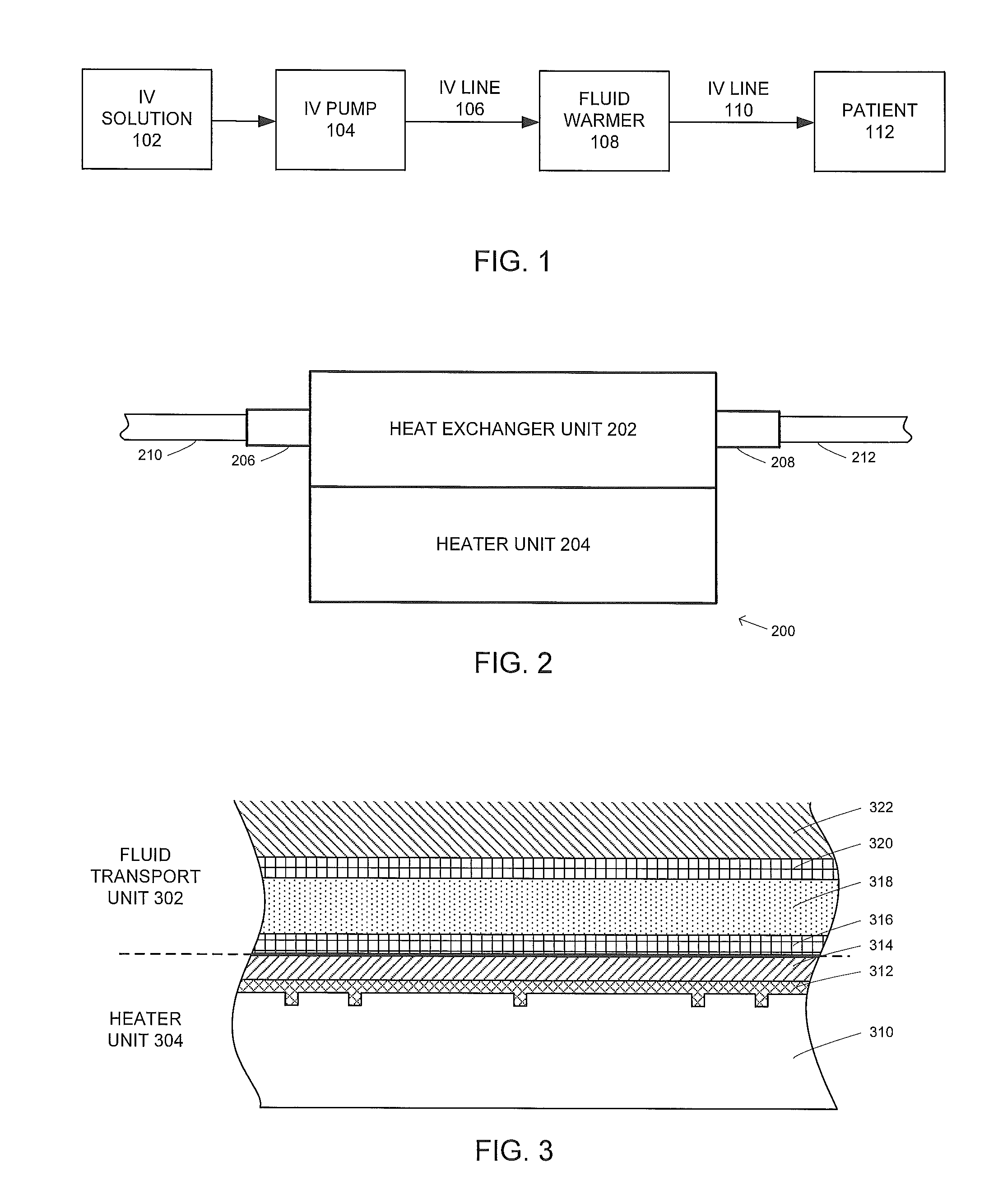
[0054]FIG. 1 is an overview of a typical application of a fluid warming system, in which an intravenous (IV) solution 102, which may for example be an aqueous solution of one or more medicines, is pumped by an optional IV pump 104 along an IV line 106 through a fluid warmer 108 and then along a further IV line 110 for intravenous insertion into the bloodstream of a patient 112. In the case of IV fluids, an outlet temperature typically in the region of 37-41° C. is desired. The IV solution may typically be presented at room temperature at around 20° C., hut this temperature may vary. The flow rate of the IV fluid is typically controlled depending on the particular medicine or other fluid to be dispensed, and in dependence on properties of a patient or other end use of the fluid.

[0055]A gravity feed can be used instead of (or in addition to) the IV pump 104. In the absence of the IV pump 104 (or otherwise) the flow rate can be increased by pressurizing a bag or other receptacle contai...


PUM


Abstract

There is disclosed a heater unit (1600) for conductively heating a removable heat exchanger unit (1602) via a heat transfer surface of the heat exchanger unit, the heater unit comprising: a body portion (1610) for receiving the heat exchanger unit (1602); a flexible heating element (1604) which, in use, makes thermal contact with the heat transfer surface of the heat exchanger unit; a compressible portion (1606) disposed on the distal side of the flexible heating element (1604) relative to the heat exchanger unit (1602) when received; and a biasing arrangement (1608) operable, in use, to distribute a transverse compression force across the arrangement formed from the compressible portion (1606), the heating element (1604) and the heat exchanger unit (1602), whereby the compression force causes the heating element (1604) to be urged towards the heat transfer surface of the heat exchanger unit (1602) and the compressible portion, in conjunction with the compression force, causes the heating element (1604) to conform more closely to the shape of the heat transfer surface.

Description

FIELD OF THE INVENTION[0001]The present invention relates to heater unit for conductively heating a removable heat exchanger unit, and a fluid warming system including such a heater unit and at least one heat exchanger unit. The invention is particularly applicable to, though not limited to, the warming of intravenous (IV) fluids for delivery to a patient.BACKGROUND TO THE INVENTION[0002]In some cases it is convenient or necessary to use a fluid warmer to heat a continuously-flowing fluid to a target temperature or range of temperatures, for example to warm intravenous (IV) fluids to body temperature before delivery to a patient.[0003]In a conventional device the fluid flows through an appropriate conduit, and a conductive heater element transfers heat to the fluid through intervening layers such as the conduit walls. In some cases, such as in the IV fluid warmer mentioned above, the conduit is releasably attachable, and may for example be a disposable cassette which is inserted int...

Claims


Application Information

Patent Timeline
Patent Type & Authority Applications(United States)
IPC IPC(8): A61M5/44F24H9/02F28F13/00F24H1/14
CPCA61M5/44F24H1/142A61M2205/3368F28F13/00F28F2013/008F24H9/02F24H9/2028A61M2205/121A61M2205/127H05B3/58H05B2203/021A61F2007/126A61M5/445F28F3/12F28D2021/005H05B3/26A61M2205/3653H05B3/20A61F7/00
Inventor BRONKHORST, JORISWIJLENS, JEROEN HERMANUS JOHANNES
Owner THE SURGICAL INT
Why Eureka
Try Eureka