Hair cutting appliance and blade set

a technology of hair cutting and blades, applied in the direction of metal working devices, etc., can solve the problems of not addressing particular shaving and trimming performance peculiarities and practical use aspects of documents

Active Publication Date: 2016-09-22
KONINKLJIJKE PHILIPS NV
View PDF10 Cites 21 Cited by
  • Summary
  • Abstract
  • Description
  • Claims
  • Application Information

AI Technical Summary

Benefits of technology

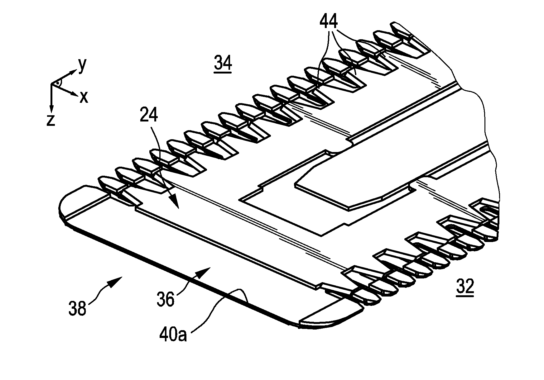
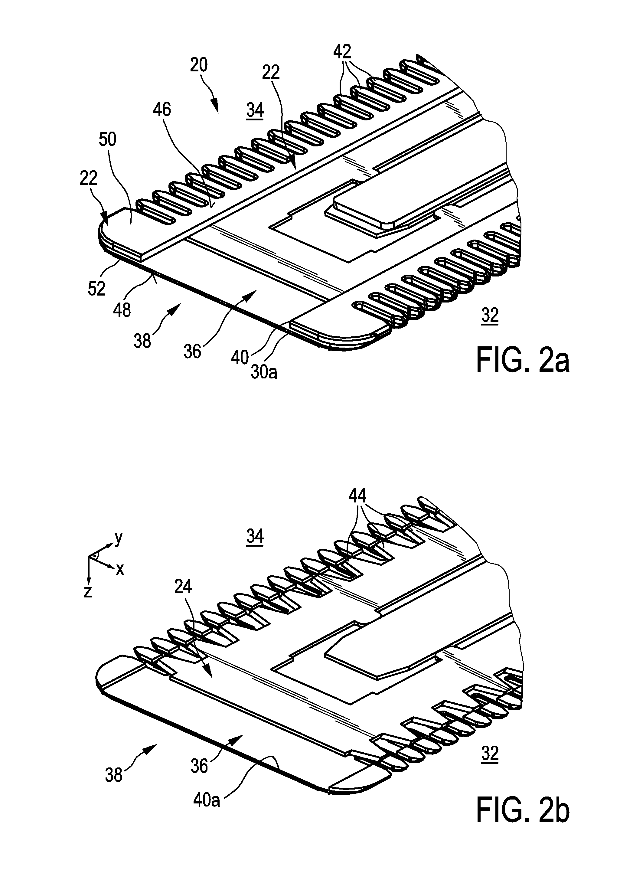
[0025]In yet another embodiment, the at least one lateral protecting element may laterally overlap the at least one of the first lateral end and the second lateral end. Consequently, the at least one protecting element may be shaped as a lateral cover or hood that, on the one hand, at least partially covers the at least one lateral end of the stationary blade and that, on the other hand, may be connected to at least some of the portions of the stationary blade that are adjoining the lateral ends thereof. This may be beneficial, since in this way a contact area between the at least one protecting element and the stationary blade may be increased. It may be, however, preferred that the overlapping portion is as small as possible so as to avoid giving away an effective lateral extension of the cutting edge. As used herein, the term “laterally overlapping” may be regarded as an at least partial overlap of the stationary blade and the at least one protecting element in the lateral direction Y.
[0026]In still another embodiment, the at least one lateral protecting element laterally adjoins the at least one of the first lateral end and the second lateral end, wherein a lateral slot defining a maximum clearance between the at least one lateral protecting element and the at least one of the first lateral end and the second lateral end is adapted to an assumed cross-sectional extension of a hair

Problems solved by technology

However, aside from that, the document does not address particular shaving and trimming pe

Method used


Image

  • Hair cutting appliance and blade set
  • Hair cutting appliance and blade set
  • Hair cutting appliance and blade set

Examples


Embodiment Construction

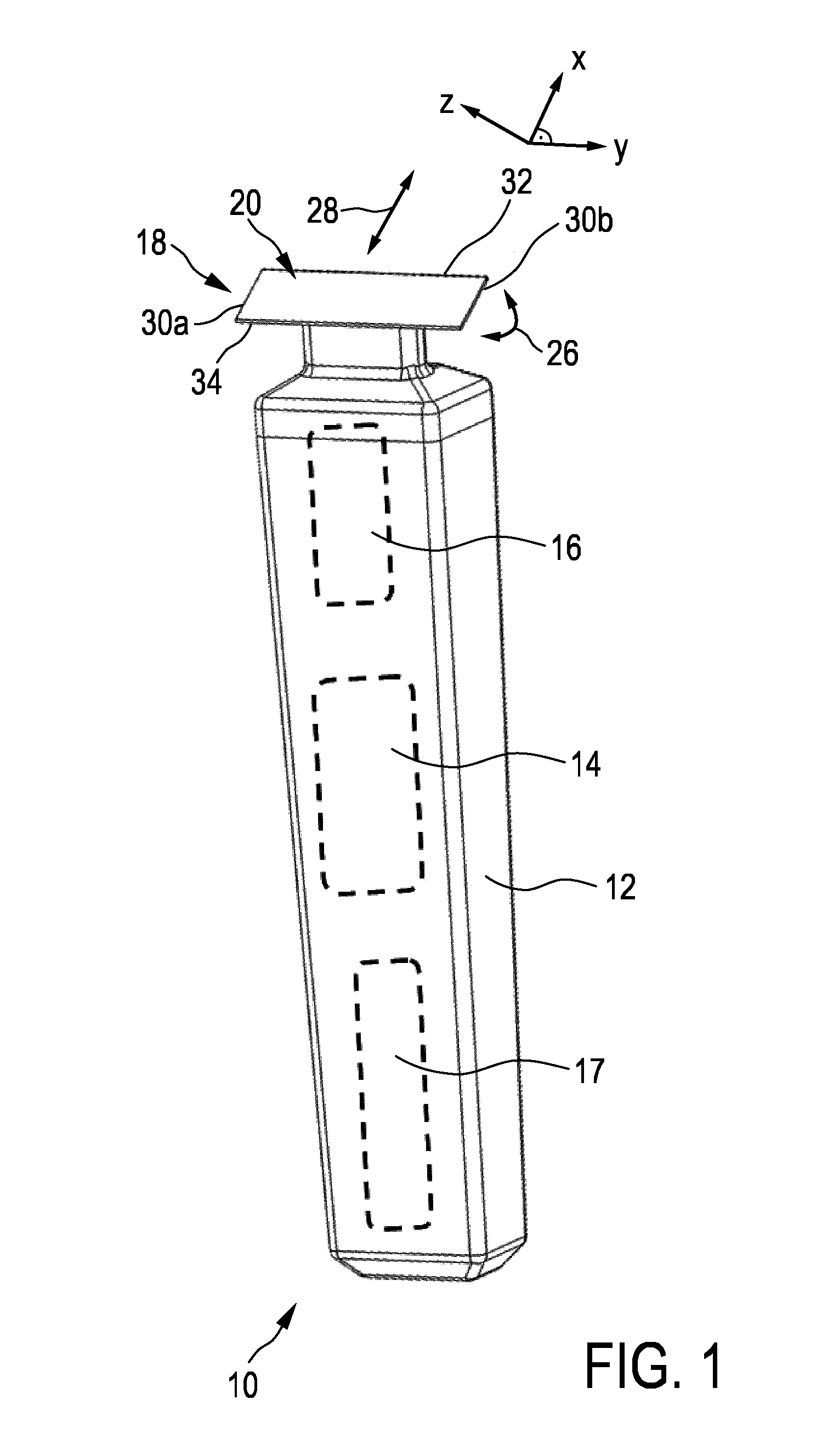
[0060]FIG. 1 schematically illustrates, in a simplified perspective view, an exemplary embodiment of a hair cutting appliance 10, particularly an electric hair cutting appliance 10. The cutting appliance 10 may include a housing 12, a motor indicated by a dashed block 14 in the housing 12, and a drive mechanism indicated by a dashed block 16 in the housing 12. For powering the motor 14, at least in some embodiments of the cutting appliance 10, an electrical battery, indicated by a dashed block 17 in the housing 12, may be provided, such as, for instance, a rechargeable battery, a replaceable battery, etc. However, in some embodiments, the cutting appliance 10 may be provided with a power cable for connecting a power supply. A power supply connector may be provided in addition or in the alternative to the (internal) electric battery 17.

[0061]The cutting appliance 10 may further comprise a cutting head or cutting unit 18. At the cutting unit 18, a blade set 20 may be attached to the h...


PUM


Abstract

The present invention relates to a hair cutting appliance (10) comprising a blade set (20), and to a blade set (20) of a hair cutting appliance (10). The blade set (20) is arranged to be moved through hair in an assumed moving direction (28) to cut hair. The blade set (20) comprises a stationary blade (22), a movable blade (24), and a lateral protecting element (56). The stationary blade (22) comprises at least one toothed cutting edge (32, 34), a lateral end (30), and a first surface (48) that is arranged, when in use for shaving purposes, as a skin-contacting surface. The movable blade (24) comprises a toothed cutting edge (32, 34). The stationary blade (22) and the movable blade (24) are arranged to be reciprocally moved with respect to each other in a cutting direction (Y) that is basically perpendicular to the assumed moving direction (28). The lateral protecting element (56) is associated with the lateral end (30), thereby defining a lateral end cap of the stationary blade (22), wherein the lateral protecting element (56) laterally shields a lateral edge (40) of the lateral end (30), such that, when in use, skin contact of the lateral edge (40) is prevented. The lateral protecting element (56) and the lateral end (30) cooperate so as to prevent hairs from being trapped there between. The stationary blade (22) and the movable blade (24) are at least partially made from steel, and the lateral protecting element (56) is made from plastic material. The blade set (20) configured to pivot or swivel with respect to a housing of the hair cutting appliance (10).

Description

FIELD OF THE INVENTION[0001]The present invention relates to a hair cutting appliance, particularly to an electrically operated hair cutting appliance, and, more particularly, to a blade set for a cutting unit for such an appliance. The blade set may comprise a stationary blade comprising at least one toothed cutting edge and a movable blade comprising at least one toothed cutting edge, wherein the stationary blade and the movable blade are arranged to be moved with respect to each other to cut hair.BACKGROUND OF THE INVENTION[0002]U.S. Pat. No. 2,290,326 A discloses a shearing assembly comprising a handle casing, a blade holder removably affixed to the forward end of said casing, said holder comprising a generally rectangular end serving as a support for a flat shearing blade assembly the shearing edges of which protrude laterally beyond the longitudinal edges of said end, a pair of clamps slidable outwardly through corresponding transverse slots along the ends of said blade holder...

Claims


Application Information

Patent Timeline
IPC IPC(8): B26B19/06B26B19/04B26B19/38
CPCB26B19/06B26B19/046B26B19/3846
Inventor BENNIK, JANVAN DER SCHEER, ROBBERT FREERK JOHANSTAPELBROEK, MARTINUS BERNARDUSAITINK, ALBERT JANHOEXUM, EVERHARDUS JOHANNES
Owner KONINKLJIJKE PHILIPS NV
Why Eureka
Try Eureka