Rotary wing aircraft with a multiple beam tail

a technology of rotary wing aircraft and tail, which is applied in the direction of aircraft, rotorcraft, aircraft components, etc., can solve the problems of reduced bending and torsional stiffness, high root stress, and high structural complexity, and achieves the reduction of structural complexity and manufacturing costs, improve functional and operational capabilities, and improve robustness

Active Publication Date: 2016-09-22
AIRBUS HELICOPTERS DEUT GMBH
View PDF6 Cites 15 Cited by
  • Summary
  • Abstract
  • Description
  • Claims
  • Application Information

AI Technical Summary

Benefits of technology

[0029]It is an objective of the invention to provide a rotary wing aircraft with an alternative tail boom configuration allowing for reductions of structural complexity and manufacturing costs while improving robustness and improving functional and operational capabilities.

Problems solved by technology

Slim cross-sections of a tail boom beam element lead to reduced bending and torsional stiffness and high root stresses at the mounting of the tail boom beam element to a fuselage of the helicopter, the bending stiffness being a potential concern in terms of the dynamic behavior of the helicopter and the root stresses being mainly a serious source of strength and fatigue issues.
On the other hand the root attachment sets important requirements on the front root structure of the tail boom in terms of fire resistance due to its integration within the engine deck area of the helicopter, leading to a higher structural complexity and the use of expensive materials and complex interface joints.
Typical tail booms are impacted by the hot exhaust gases of the helicopter's engines, especially during hover, setting important requirements to the choice of structural materials in terms of their heat resistance which translates to less design flexibility and larger material costs.
The disassembly of a typical continuous circumferential joint of a single tail boom beam element with a large amount of fasteners from a fuselage or the integration of pivotable features between a single tail boom beam element and a fuselage is complex.
The integration of pivotable features within conventional tail booms is inefficient since it does not allow large folding angles relative to a fuselage due to the central arrangement of the tail booms with cross-sections widths considerably smaller than the width of the fuselage.
Integrated tail booms shaped as a smooth continuation of the fuselage hull lead to reductions in drag during forward flight but, on contrary, to an increase of down-load in the hover.
A streamlined tail boom may be practical on executive transports, but for other purposes rear loading ramps or clamshell doors may be needed which result in typical pod and boom designs with higher drag during forward flight.
The integration of pivotable or dismountable streamlined tail booms lead moreover to a considerable structural weight increase and to less efficient folding characteristics.
A typical cylindrical shape of a tail boom is optimal for torsional stiffness but it is generally less efficient when subjected to a transverse flow.
The unstable characteristics of a transverse airflow across a cylindrical shape are a possible source of shaking in the hover of the helicopter, which is a phenomenon directly linked to the bending stiffness of the tail boom.
The cross section is however larger than that of the first design hence leading to increased down-loads generated by the down-wash of the main rotor.
Typical folding capabilities are limited to the folding of the blades rearwardly and the folding of a rear portion of the tail forwardly.
The configuration requires a direct mechanical power transmission from the powerplant to the tail rotor (deflections require heavy gear boxes) intensive maintenance and continuous inspection.

Method used


Image

  • Rotary wing aircraft with a multiple beam tail
  • Rotary wing aircraft with a multiple beam tail
  • Rotary wing aircraft with a multiple beam tail

Examples


Embodiment Construction

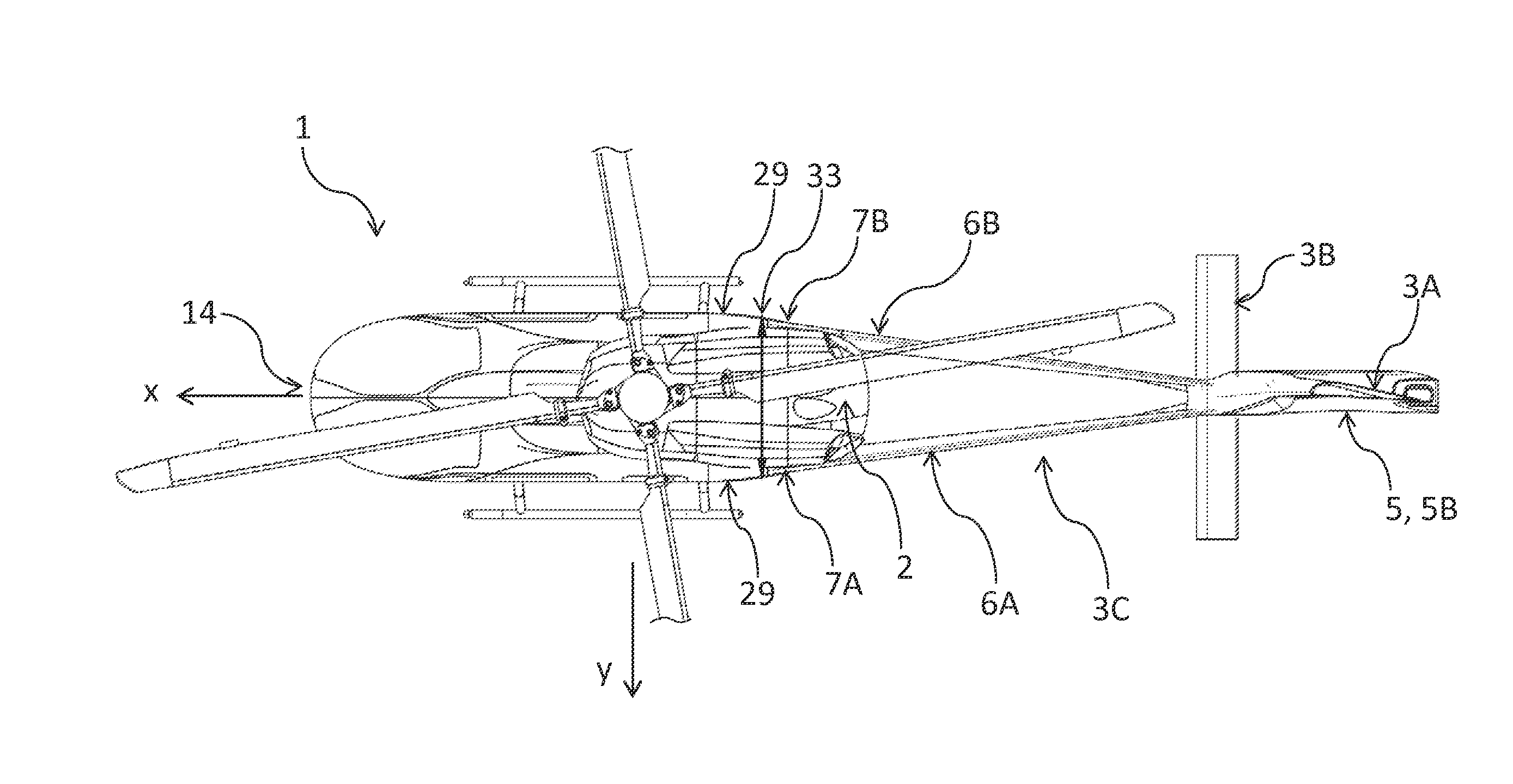
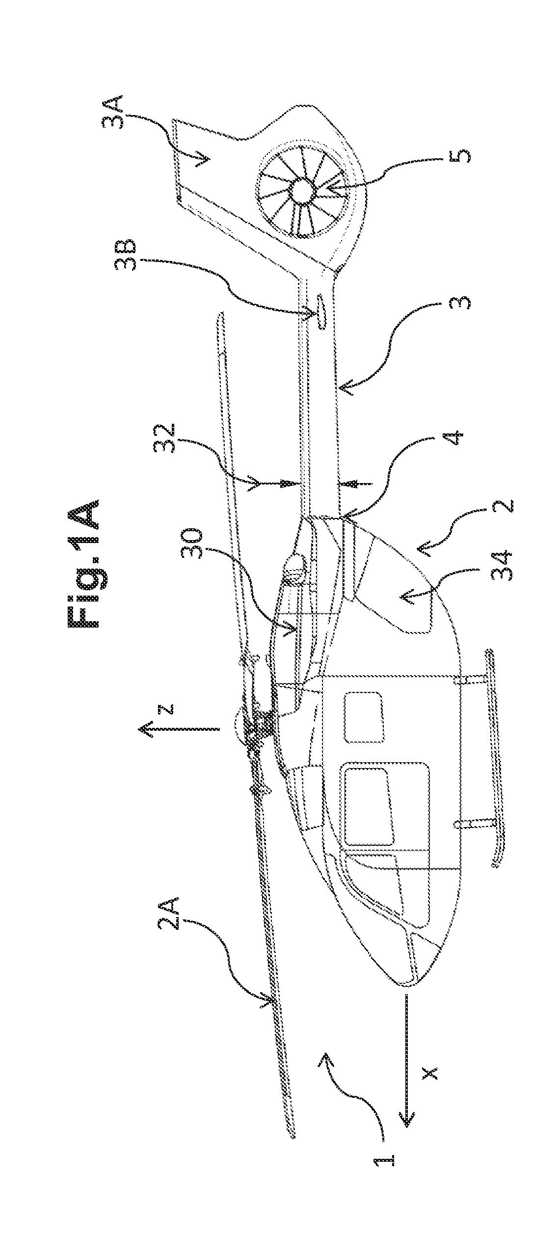
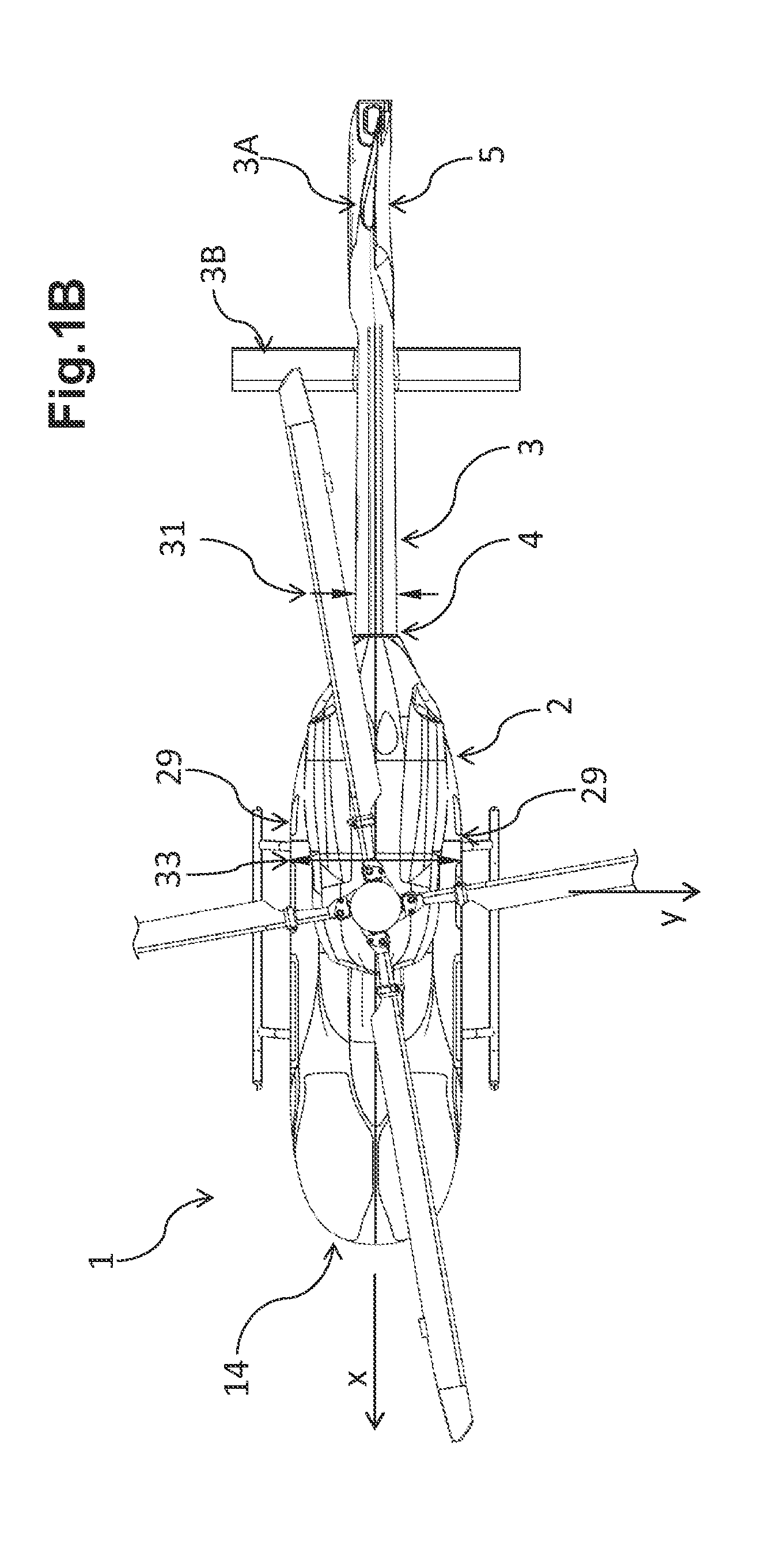
[0082]According to FIGS. 1A and 1B a known rotary wing aircraft 1 of the helicopter type comprises a fuselage 2 and a single central tail boom 3 in conventional cantilever configuration mounted to a rear part of said fuselage 2. A main rotor 2A is mounted to a top deck of the fuselage 2. The single central tail boom 3 comprises a fin 3A and one or a plurality of horizontal planes 3B, at the very aft end of the tail boom. The single central tail boom 3 has a height 32 and a width 31 and it is attached to the rear part of the fuselage 2 at a tail boom root 4. The rear part of said fuselage 2 is provided with a rear access door 34. The fin 3A is generally vertical, is attached to a rear end of the tail boom 3 and houses a tail rotor 5 (here of Fenestron © type). The width 31 of the tail boom 3 is considerably less than a fuselage width 33. Engines 30 for driving the rotors 2A, 5 are allocated in an engine deck of the rear part of said fuselage 2.

[0083]FIGS. 2-7 illustrate embodiments o...


PUM


Abstract

A rotary wing aircraft comprising a fuselage, a cabin volume enclosed by the fuselage, a main rotor arranged above the fuselage, a tail rotor mounted on a tail, the tail being attached to a rear part of the fuselage supporting the tail at its rear end, whereas the tail includes two beam boom elements, one element extending at the port side and the other element extending at the starboard side of the rotary wing aircraft, the front root end of each element being hinged to the corresponding lateral side of the fuselage, and both elements being canted with respect to the longitudinal axis of the rotary wing aircraft so as to be interconnected to each other at the rear portion of the tail.

Description

CROSS REFERENCE TO RELATED APPLICATION[0001]This application claims priority to European patent application No. EP 14 400026.2 filed on Apr. 15, 2014, the disclosure of which is incorporated in its entirety by reference herein.BACKGROUND OF THE INVENTION[0002](1) Field of the Invention[0003]The invention relates to a rotary wing aircraft with a tail supporting a tail rotor, possibly at least one tail rotor being an electrically driven tail rotor.[0004](2) Description of Related Art[0005]The dominant rotary wing aircraft configuration in the present time is based on helicopter basic design including a single main rotor and an auxiliary tail rotor to counter torque and provide directional yaw control. The tail rotor is mounted at the rear end of a supporting structure—the tail boom—behind the main fuselage. This tail boom is typically a single beam element.[0006]A fin arranged at the same location as the tail rotor provides for directional stability during forward flight hence relievi...

Claims


Application Information

Patent Timeline
Patent Type & Authority Applications(United States)
IPC IPC(8): B64C1/06B64C1/26B64C27/82
CPCB64C1/063B64C27/82B64C2027/8209B64C2027/8254B64C2027/8263B64C1/26
Inventor FINK, AXEL
Owner AIRBUS HELICOPTERS DEUT GMBH
Why Eureka
Try Eureka