Method of suppressing metal contamination of synthesis gas production apparatus

a technology of synthesis gas production apparatus and metal contamination, which is applied in the direction of combustible gas purification/modification, hydrogen separation using liquid contact, energy input, etc., can solve the problems of affecting the operation of the machine, affecting the efficiency of the machine, so as to prevent the catalyst activity and operate stably

Active Publication Date: 2016-09-22
JAPAN OIL GAS & METALS NAT CORP +6
View PDF1 Cites 12 Cited by
  • Summary
  • Abstract
  • Description
  • Claims
  • Application Information

AI Technical Summary

Benefits of technology

[0009]In view of the above-identified circumstances, an object of the present invention is to reduce as the nickel carbonyl contained in the carbon dioxide as possible that is being recycled from the carbon dioxide separation / collection step to the synthesis gas production step, and prevent the reforming catalyst from being deteriorated due to causing the nickel to accelerate the carbon producing reaction in the reformer in the synthesis gas production step.
[0010]According to the present invention, the above object is achieved by providing a method of suppressing metal contamination of a synthesis gas production apparatus operating for a GTL (gas-to-liquid) process, including: a synthesis gas production step of producing synthesis gas by causing natural gas and gas containing steam and / or carbon dioxide to react with each other for reforming in a synthesis gas production apparatus; a Fischer-Tropsch oil manufacturing step of manufacturing Fischer-Tropsch oil by subjecting the synthesis gas produced in the synthesis gas production step to a Fischer-Tropsch reaction and subsequently isolating a gaseous product from the Fischer-Tropsch reaction products; and an upgrading step of manufacturing various hydrocarbon oils by subjecting the Fischer-Tropsch oil manufactured in the Fischer-Tropsch oil manufacturing step to hydrotreatment and distillation, in which, at the time of separating and collecting a carbon dioxide contained in the synthesis gas produced in the synthesis gas production step and recycling the separated and collected carbon dioxide as source gas for the reforming reaction in the synthesis gas production step, a nickel concentration in the recycled carbon dioxide is not higher than 0.05 ppmv.
[0011]Thus, according to the present invention, the nickel carbonyl concentration in the carbon dioxide recycled to the reformer in the synthesis gas production step of a GTL process is minimized and hence the carbon deposition and accumulation on the surface of the reforming catalyst for producing synthesis gas filled in the reformer is suppressed (prevented) to prevent the catalyst activity of the reforming catalyst from being degraded. Additionally, adhesion of nickel to the machines, such as compressors and heat exchangers, in the synthesis gas production step is suppressed (prevented) to allow the machines to stably operate for a long period.

Problems solved by technology

Depletion of petroleum resources have been feared for a long period.
Then, degradation of the catalyst activity of the reforming catalyst is feared.
Then, damages to those machines are feared because such damages can adversely affect the stable and long term operation of the machines.

Method used


Image

  • Method of suppressing metal contamination of synthesis gas production apparatus
  • Method of suppressing metal contamination of synthesis gas production apparatus
  • Method of suppressing metal contamination of synthesis gas production apparatus

Examples


example 1

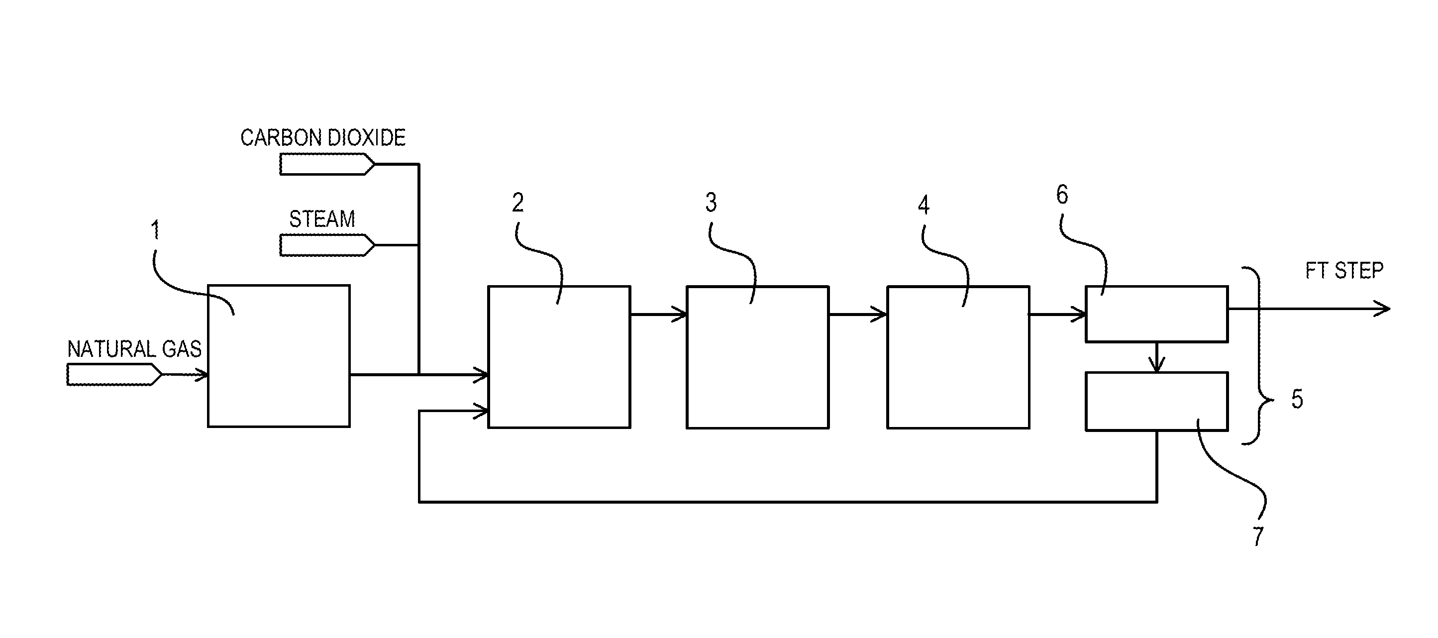
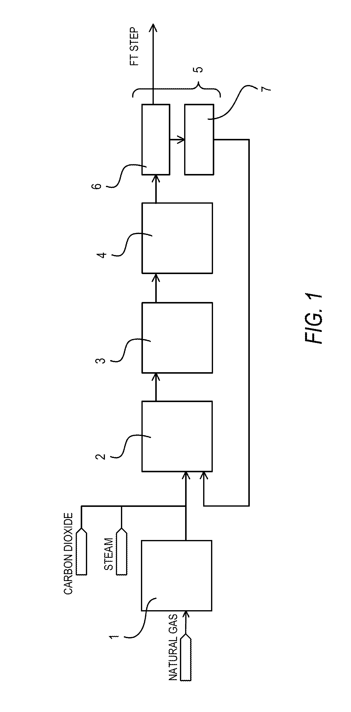
[0032]Synthesis gas was produced by introducing natural gas, to which steam and carbon dioxide were added to make the H2O / C mol ratio and the CO2 / C mol ratio respectively equal to 1.1 and 0.4, into a reformer filled with a reforming catalyst formed by supporting a VIII group metal on an alkaline-earth metal oxide carrier under conditions of an inlet temperature of 500° C., an outlet temperature of 880° C., a pressure of 2.0 MPaG, and a GHSV of 3,000 h−1. The obtained synthesis gas (H2: 58%, CO: 28%, CO2: 7%, CH4: 7%) was then introduced into a carbon dioxide absorption tower under conditions of a temperature of 40° C. and a pressure of 2 MPaG in order to separate and collect CO2 from the obtained synthesis gas. The carbon dioxide absorption tower 6 was of a filled tower type. In other words, it was filled with cascade mini-rings of SUS410, which is a stainless steel material containing no nickel. The introduced synthesis gas was brought into gas / liquid contact with an aqueous soluti...

example 2

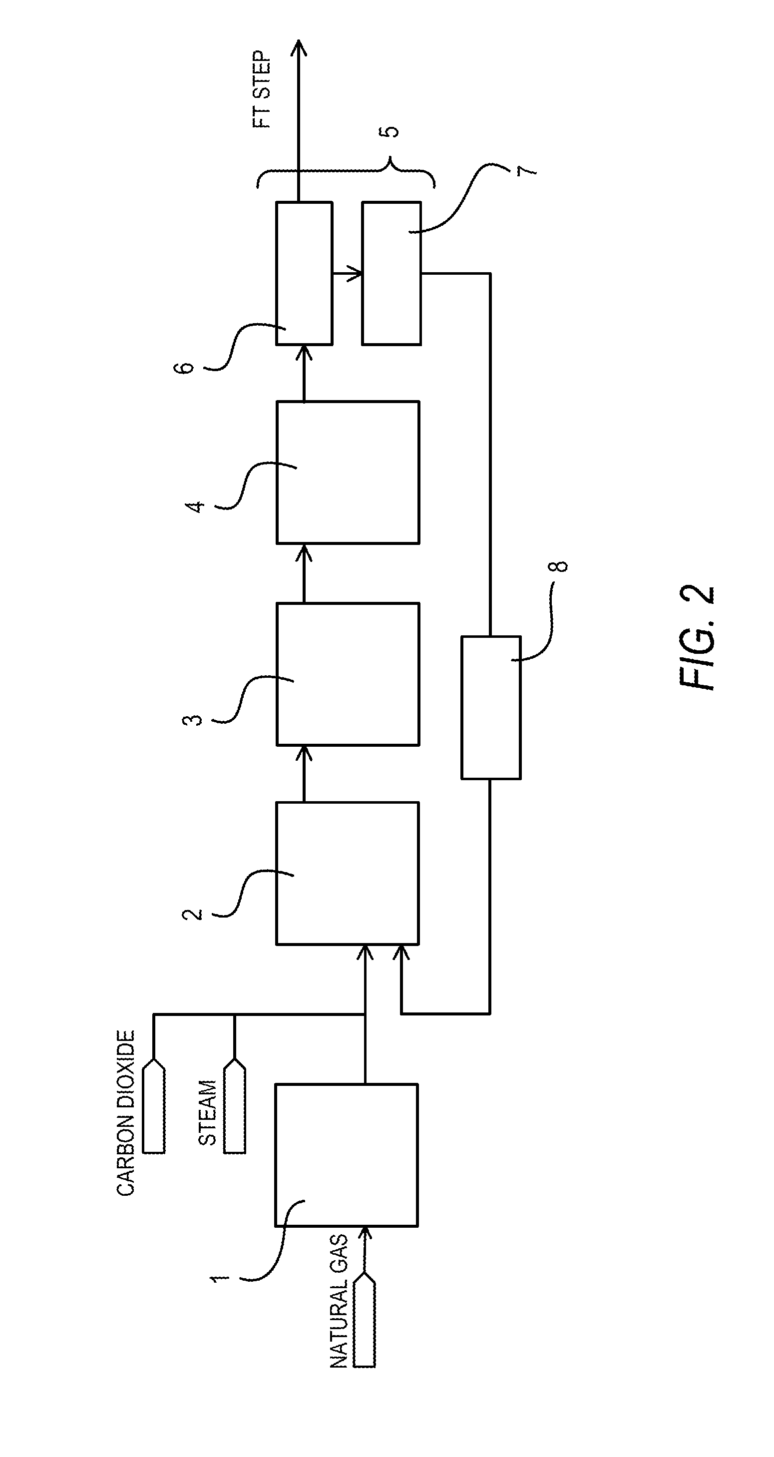
[0034]The pressure of the carbon dioxide (the nickel carbonyl concentration was 2.0 ppmv in terms of nickel metal) collected in Comparative Example 1 was raised to 2.2 MPaG and subsequently the carbon dioxide was heated to 250° C. The heated carbon dioxide was made to pass through an adsorption apparatus filled with a nickel carbonyl adsorbing material (Actisorb400: tradename, available from Süd-Chemie Catalysts) at a GHSV of 1,500 h−1. As a result, the nickel carbonyl concentration in the carbon dioxide was reduced to 0.02 ppmv in terms of nickel metal.

[0035]This application claims the benefit of Japanese Patent Application No. 2011-078808, filed Mar. 31, 2011, which is hereby incorporated by reference herein in its entirety.


PUM

PropertyMeasurementUnit
concentrationaaaaaaaaaa
catalyst activityaaaaaaaaaa
adhesionaaaaaaaaaa

Abstract

A synthesis gas production apparatus (reformer) to be used for a synthesis gas production step in a GTL (gas-to-liquid) process is prevented from being contaminated by metal components. A method of suppressing metal contamination of a synthesis gas production apparatus operating for a GTL process that includes a synthesis gas production step of producing synthesis gas by causing natural gas and gas containing steam and / or carbon dioxide to react with each other for reforming in a synthesis gas production apparatus in which, at the time of separating and collecting a carbon dioxide contained in the synthesis gas produced in the synthesis gas production step and recycling the separated and collected carbon dioxide as source gas for the reforming reaction in the synthesis gas production step, a nickel concentration in the recycled carbon dioxide is not higher than 0.05 ppmv.

Description

CROSS-REFERENCE TO RELATED APPLICATIONS[0001]This is a divisional of U.S. application Ser. No. 14 / 008,509, filed Sep. 27, 2013, which is a 371 of PCT / JP2012 / 001966, filed Mar. 22, 2012, which claims priority to JP 2011-078808, filed Mar. 31, 2011, the entire contents of which is incorporated herein by reference.TECHNICAL FIELD[0002]The present invention relates to a method of suppressing metal contamination of a synthesis gas production apparatus. More particularly, the present invention relates to a method of preventing nickel contamination of a synthesis gas production apparatus in a synthesis gas production step of a GTL (gas-to-liquid) process.BACKGROUND ART[0003]Depletion of petroleum resources have been feared for a long period. Meanwhile, research efforts have been made for technologies of manufacturing various hydrocarbon oils such as naphtha, kerosene and gas oil by exploiting natural gas, coal and alternative carbon sources such as biomass in order to reduce the degree of ...

Claims


Application Information

Patent Timeline
Patent Type & Authority Applications(United States)
IPC IPC(8): C10G2/00C10K1/00C10G49/00C10G45/00C01B3/38C01B3/54C01B32/50
CPCC10G2/30C01B3/38C01B3/54C10G49/00C10G45/00C10K1/005C01B2203/1241C01B2203/0238C01B2203/0475C01B2203/0415C01B2203/0435C01B2203/062C01B2203/0233C01B3/384C10G2300/4081C01B2203/0894C01B2203/1047C01B2203/1258C01B2203/148C10G2300/1025C01B2203/0465C01B2203/0811C01B2203/1082Y02P20/129C10K1/007Y02C20/40
Inventor WAKAMATSU, SHUHEIYAGI, FUYUKIMIKURIYA, TOMOYUKIKAWAZUISHI, KENICHI
Owner JAPAN OIL GAS & METALS NAT CORP
Why Eureka
Try Eureka