
Circuit device, physical-quantity detecting apparatus, electronic apparatus, and moving object

Active Publication Date: 2016-09-22
SEIKO EPSON CORP
View PDF20 Cites 11 Cited by
  • Summary
  • Abstract
  • Description
  • Claims
  • Application Information

AI Technical Summary

Benefits of technology

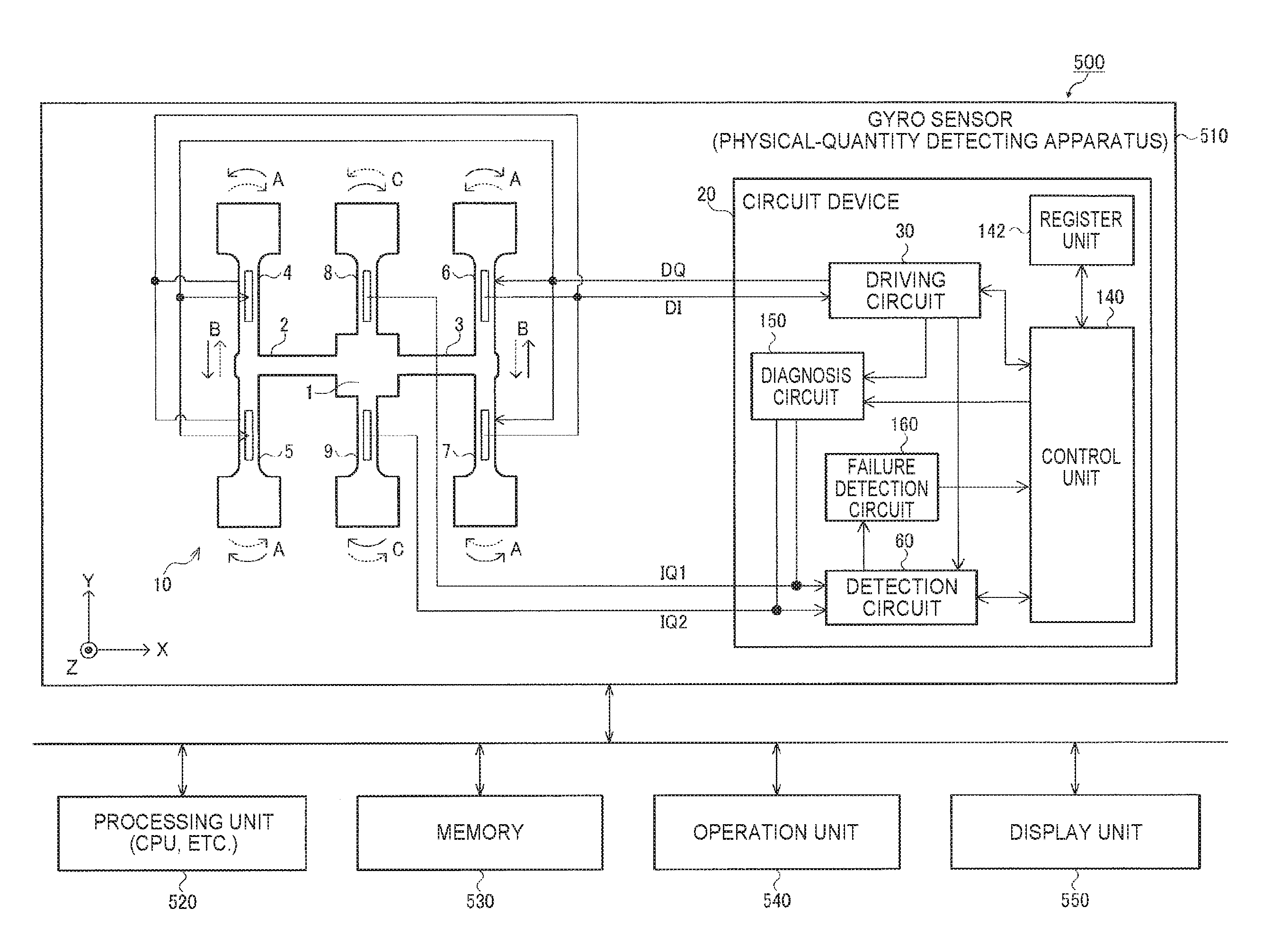
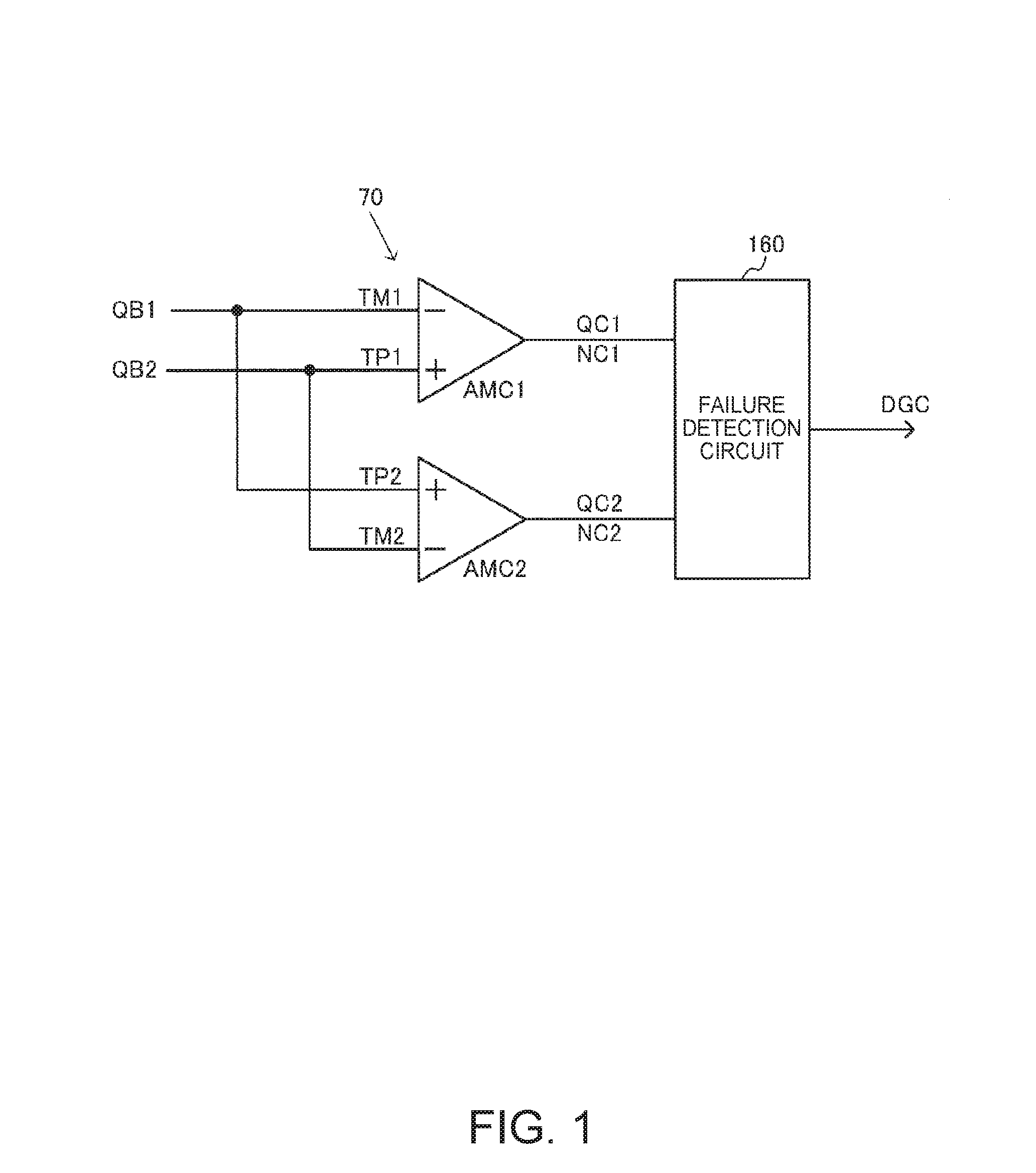
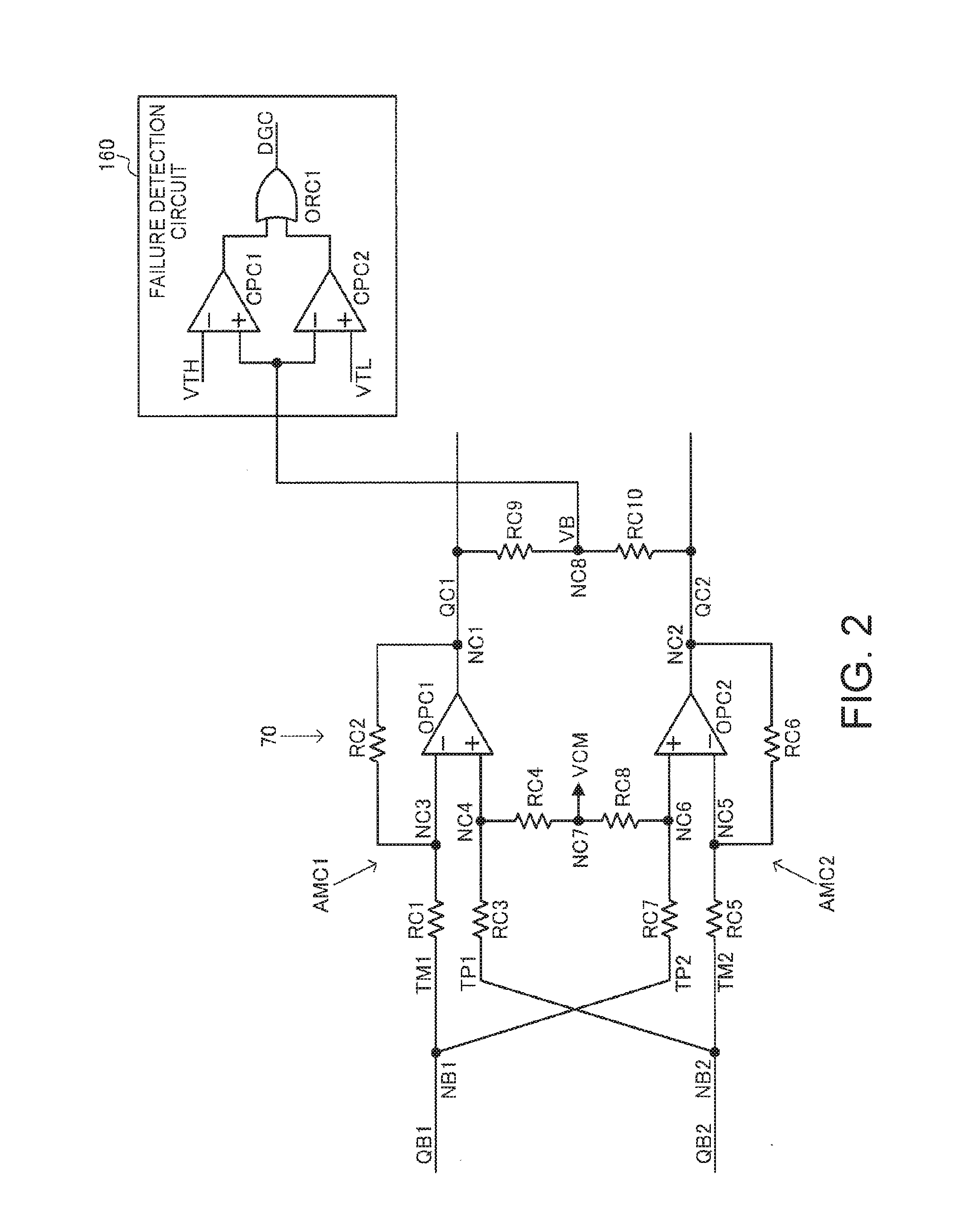
The invention relates to a circuit device that includes two amplifiers, one of which performs differential input and the other of which performs inversion input. The device also includes a failure detection circuit that detects failures based on the output of the first amplifier and the output of the second amplifier. This prevents failures from being overlooked when a differential-signal processing circuit is configured using a single differential input / differential output amplifier. The failure detection circuit detects whether the monitoring voltage based on the output signals of the amplifiers is within a determination voltage range. This allows for the determination of whether the circuit device is in a normal state or likely to have failed. The device may perform differential output based on the same analog common voltage, and the monitoring voltage may be set based on the analog common voltage. The technical effect of this invention is to provide a reliable and effective circuit device for differential-signal processing.

Problems solved by technology

However, in the past, failure detection of the differential-signal processing circuit cannot be performed.
For example, although failure detection of the entire detection circuit is possible, a failure of the differential-signal processing circuit cannot be individually detected.
For example, when a differential component is seen as being normally differentially amplified, although the differential-signal processing circuit is actually out of order, proper failure detection of the differential-signal processing circuit cannot be realized by the failure detection of the entire detection circuit.
Therefore, when a failure occurs over time in the differential-signal processing circuit while the circuit device is actually operating, appropriate measures cannot be taken against the failure.
As a result, for example, deterioration in reliability occurs.

Method used


Image

  • Circuit device, physical-quantity detecting apparatus, electronic apparatus, and moving object
  • Circuit device, physical-quantity detecting apparatus, electronic apparatus, and moving object
  • Circuit device, physical-quantity detecting apparatus, electronic apparatus, and moving object

Examples


second embodiment

[0222]A circuit device according to a second embodiment of the invention is explained below. However, in some case, components same as the components of the circuit device 20 according to the first embodiment are denoted by the same reference numerals and signs and explanation of the components is omitted.

1. A Circuit Device

[0223]A basic configuration example of the circuit device according to the second embodiment is shown in FIG. 12. The circuit device according to this embodiment includes the first and second operational amplifiers OPD1 and OPD2 and first and second voltage division circuits 77 and 78. A gain adjustment amplifier 76a (in a broad sense, a differential-signal processing circuit) is configured by the first and second operational amplifiers OPD1 and OPD2 and the first and second voltage division circuits 77 and 78. Further, the circuit device according to this embodiment includes a failure detection circuit 160a.

[0224]The first signal QC1 of the first and second sig...


PUM


Abstract

A circuit device includes a differential input-to-single-ended output first amplifier, to an inversion input terminal of which, of first and second signals forming differential signals, the first signal is input and to a non-inversion input terminal of which the second signal is input, a differential input-to-single-ended output second amplifier, to a non-inversion input terminal of which the first signal is input and to an inversion input terminal of which the second signal is input, and a failure detection circuit that performs failure detection on the basis of an output signal of the first amplifier and an output signal of the second amplifier.

Description

BACKGROUND[0001]1. Technical Field[0002]The present invention relates to a circuit device, a physical-quantity detecting apparatus, an electronic apparatus, a moving object, and the like.[0003]2. Related Art[0004]There has been known a circuit device that detects a physical quantity on the basis of a detection signal from a physical quantity transducer. Taking a gyro sensor as an example, the circuit device detects angular velocity and the like as physical quantities. The gyro sensor is incorporated in electronic apparatuses such as a digital camera and a smart phone and moving objects such as a car and an airplane. Camera shake correction, posture control, GPS autonomous navigation, and the like are performed using detected physical quantities such as angular velocity.[0005]As the circuit device of such a gyro sensor, for example, there is a technique disclosed in JP-A-2008-122122.[0006]In JP-A-2008-122122, a differential-signal processing circuit such as a differential amplifier c...

Claims


Application Information

Patent Timeline
IPC IPC(8): H03F3/45G01C19/5642H03K5/24
CPCH03F3/45076H03K5/24H03F2203/45118H03F2200/129G01C19/5642G01C19/5726G01C19/5776H03F3/45475H03F2200/261H03F2203/45138H03F2203/45522H03F2203/45526H03F2203/45528G01D3/08
Inventor AOYAMA, TAKASHI
Owner SEIKO EPSON CORP
Learn More