System and method for UV-led liquid monitoring and treatment

Active Publication Date: 2016-09-29
LARQ INC
View PDF5 Cites 21 Cited by
  • Summary
  • Abstract
  • Description
  • Claims
  • Application Information

AI Technical Summary

Benefits of technology

[0008]In various embodiments, a communication portion may include a communication system based upon Bluetooth, WiFi, 4G, 3G, NFC, RF, Ethernet, or the like. The communication portion may directly communicate to a cloud-based reporting server via WiFi, 4G, 3G, Ethernet, or the like. In other embodiments, the communication portion communicates via Bluetooth, NFC, IR, ZigBee or other rf protocol to a smart device (e.g. smart phone, home PC, home server, or the like) having one or more specialized software applications running thereon. In various embodiments, the water data may be stored within the applications, processed and viewed by the user on the smart device. For example, the user may see time trends in the water turbidity, the types of contaminants detected in the water, and the like. In some embodiments, the data may automatically or manually uploaded to the centralized reporting server from the application. For example, the user's application may periodically upload the water quality data captured, as described herein.
[0009]In various embodiments, a centralized reporting server receives and stores water quality reports from a multitude of users in real-time or non-real time. Based upon the real-time and/or non-real time data and based upon knowledge of the water distribution network, near-real time identification of water quality problems may be determined. Causes for the water quality problems may then be investigated, and fixes to the distribution network, modifications to the outgoing water treatment, and other actions may be taken. Further, based upon knowledge of the water distribution network and the water quality reports, over time, trends in water quality may be determined. Based upon the trends, a water provider may change its water purification procedures (e.g. add additional chemical removal steps); may determine water branches having unusual contaminants, inspect the water branches, and/or repair faulty water branches; may shut-off water provided to specific branches or shut-off water from specific sources when contaminants exceed the purification capabilities; may modify conditions around aquifers and other water sources, and the like.
[0010]According to one aspect of the invention, an apparatus for providing water is disclosed. One device includes a water input portion configured to receive untreated water having biological and chemical impurities, and a water treatment portion configured to receive the untreated water and to output treated water. In some embodiments, a water treatment portion includes a UV disinfection/treatment module configured to reduce the biological impurities in the untreated water, and a filtering mechanism configured to reduce the chemical impurities in the untreated water. A system may include a UV analysis module configured to determine initial levels of the biological impurities and the chemical impurities in the untreated water and to determine treated levels of the biological impurities and chemical impurities in the treated water, or the optical transmittance of the untreated water, or the optical absorbance of the untreated water, and a processing unit coupled to the UV analysis module, wherein the processing unit is configured to determine whether the treated levels of the biological impurities or the chemical impurities in the treated water exceed at least one threshold and to provide a impurity signal in response thereto. An apparatus may include a reporting module coupled to the processing unit, wherein the reporting module is configured to output the initial levels of the biological impurities and the chemical impurities and the treated levels of the biological impurities and the chemical impurities to a remote monitoring service, and a water output portion coupled to processing unit, wherein the output portion is configured to allow output of the treated water, and wherein the output portion is configured to inhibit output of the treated water in response to the impurity signal.
[0011]According to one aspect of the invention, a water monitoring system is disclosed. A system may include a plurality of water quality monitoring devices located at a plurality of geographically remote locations. In some aspects, water qua

Problems solved by technology

In general, it is contemplated that unsanitary water may include water of unknown-safety, pathogen-bearing wa

Method used


Image

  • System and method for UV-led liquid monitoring and treatment
  • System and method for UV-led liquid monitoring and treatment
  • System and method for UV-led liquid monitoring and treatment

Examples


Embodiment Construction

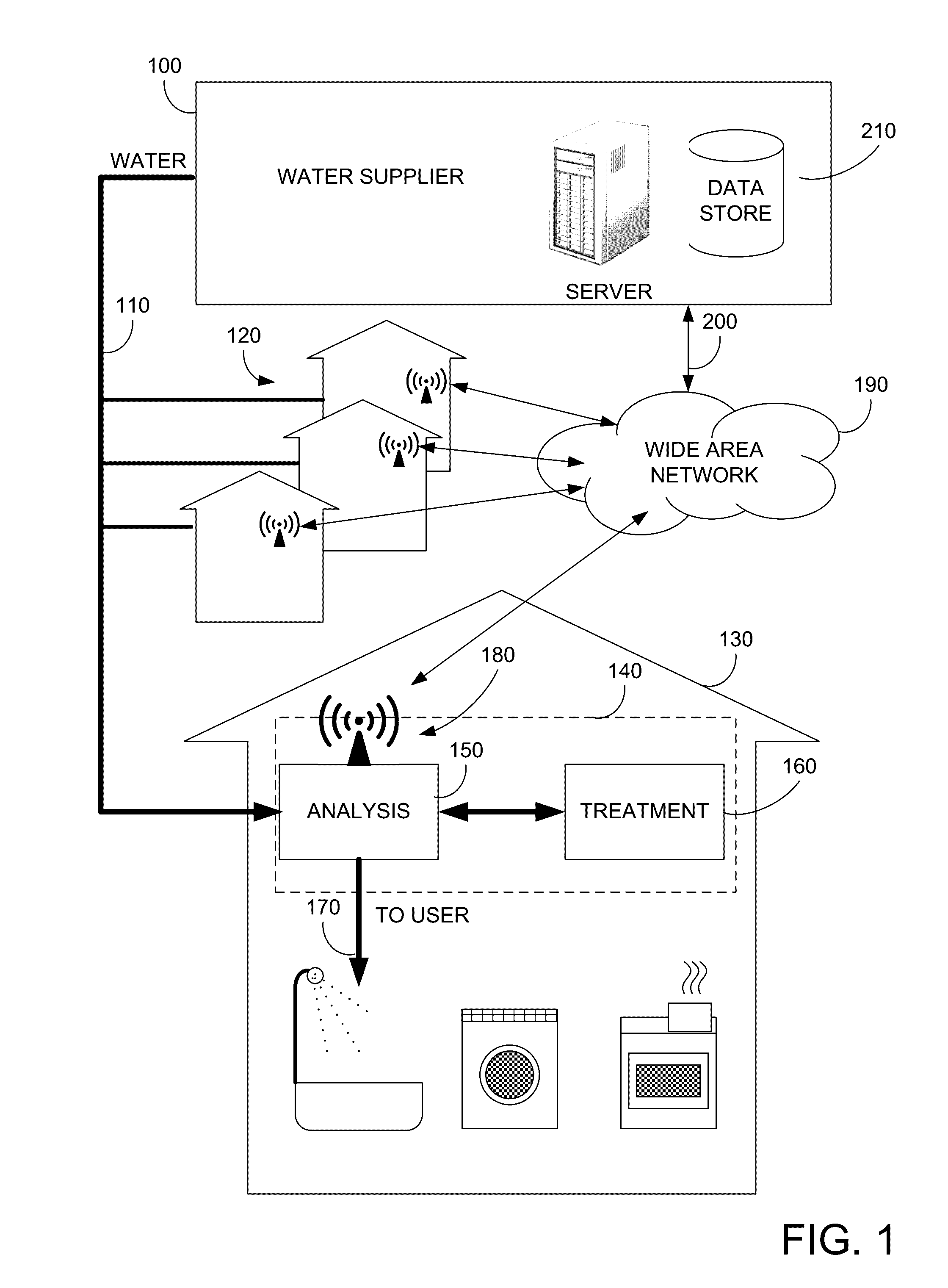
[0020]FIG. 1 illustrates an embodiment of the present invention. More specifically, FIG. 1 illustrates a water supplier 100 supplying water 110 to water customers 120. Within a typical water customer 130, a is provided. In the present example, device 140 includes a water analysis device 150 and a water treatment device 160. As will be discussed further below, water analysis device 150 can perform an impurity analysis or optical transmittance, or optical absorbance analysis on incoming water 110, and water treatment device 160 can treat incoming water 110 and output treated water 170. Water analysis device 150 can also perform an impurity analysis or optical transmittance, or optical absorbance analysis on the treated water 170. If the treated water 170 is within predetermined impurity thresholds, it may be provided to the user, and in some embodiments, if the treated water exceeds the predetermined impurity thresholds, the treated water 170 will not be provided to the user.

[0021]In ...


PUM


Abstract

An water providing apparatus includes a input portion for receiving untreated water, a treatment portion for treating and outputting treated water having a UV treatment module for reducing pathogens, a filtering mechanism for reducing physical and chemical impurities, a UV analysis module for determining levels of the impurities in the untreated water and for determining levels of impurities in the treated water, a processing unit for determining whether the levels of impurities in the treated water exceed a threshold, a reporting module for outputting the levels of the impurities in the untreated and treated water to a remote monitoring service, and a water output portion for providing the treated water if safe, and for inhibiting output of the treated water if unsafe.

Description

BACKGROUND OF THE INVENTION[0001]The present invention relates to liquid monitoring. More specifically, embodiments of the present invention relate to a UV-LED liquid monitoring and purification systems and methods of operation.[0002]Water suppliers periodically monitor water quality at centralized locations, such as water treatment plants, pump stations, and the like. The periodic testing is used to check whether the provided water meets certain health quality standards.[0003]The inventors of the present invention believe that there are drawbacks to centralized testing systems including that water delivered to the end point (consumer), e.g. home, apartment, factory, or the like, may not have the same quality as provided by the supplier. Reasons for this deterioration in quality may include contamination within the distribution network (e.g. leaky pipes, pollution, sewage contamination, etc.); contamination within an end point (e.g. leaky pipes within a factory, chemicals leached fr...

Claims


Application Information

Patent Timeline
IPC IPC(8): C02F1/00C02F1/72C02F1/32
CPCC02F1/008C02F1/325C02F1/725C02F1/001C02F2305/10C02F2209/008C02F2201/008C02F2209/36C02F2303/04C02F2201/009C02F2201/326C02F1/004C02F2201/3222C02F2201/3227C02F2209/001C02F2209/003C02F2209/08C02F2209/11C02F2209/15C02F2209/20C02F2209/21Y02W10/37
Inventor LIAO, YITAOWALKER, ROBERTCOLLINS, DOUGDE JONY, THEODORE
Owner LARQ INC
Why Eureka
Try Eureka