
Parallel transmission by spin dynamic fingerprinting

a fingerprinting and parallel transmission technology, applied in the field of magnetic resonance imaging, can solve the problems of strong aliasing artifacts, contrast artifacts and shading areas, and undesirable non-uniform transmitting sensitivity,

Active Publication Date: 2016-09-29
NEW YORK UNIV
View PDF5 Cites 21 Cited by
  • Summary
  • Abstract
  • Description
  • Claims
  • Application Information

AI Technical Summary

Benefits of technology

The patent describes a system for whole body magnetic resonance imaging that uses multiple radio frequency transmitters to produce distinct signals for identifying different materials. This system can be used for fingerprinting materials in the absence of strong non-uniformities and can include a processor and computer-readable medium for searching a database for a closest match to the received magnetic resonance information. The technical effect of this system is that it provides a more accurate way to identify materials using magnetic resonance imaging.

Problems solved by technology

Traditionally, non-uniformities in the transmit-sensitivity are considered undesirable, giving rise to contrast artifacts and areas of shading in the final image.
This results in strong aliasing artifacts.
However, the Larmor frequency increases linearly with field strength, resulting in increasingly significant interactions between applied radiofrequency (RF) fields and tissue.
For certain systems the RF wavelength is comparable to the dimensions of the human torso, resulting in contrast artifacts and areas with signal voids in the abdomen (Bernstein, et al., 2006).
Considering research systems currently operating at 7 to 11.7 Tesla, strong RF interference effects result in extremely non-uniform transmit-sensitivity (B1+(r)) profiles (Yang, et al., 2002).
However, they highlight that this is extremely tedious due to the tendency of non-uniform transmit-sensitivity profiles to form contrast artifacts.
Consequently, both the acquisition speed and the obtainable contrast, both high priorities for clinical imaging, are greatly impaired.

Method used


Image

  • Parallel transmission by spin dynamic fingerprinting
  • Parallel transmission by spin dynamic fingerprinting
  • Parallel transmission by spin dynamic fingerprinting

Examples


experimental examples

Additional Experimental Examples

[0067]Further, under some circumstances, complex electrodynamic interactions between a subject and an incident RF field may distort RF excitation to such an extent that the diagnostic value of MRI be compromised (Bernstein, 2006). Metal implants, in particular, are a source of MR artifacts, resulting not only from distortion of the main magnetic field, but also from distortions of the excitation RF field (Graf et al., 2005). In at least one example, the potential of a generalized implementation of a proposed plug & play parallel transmission (PTX) framework (Cloos et al., 2014) was considered to enable rapid multiparamatric mapping (T1, T2, PD) in the presence of orthopedic implants.

[0068]Methods:

[0069]At 3 Tesla, large metal implants such as the titanium rod depicted in FIG. 11A may interact significantly with the incident RF field. Depending on the polarization of the applied RF field, different reactive fields are produced, which in turn perturb th...


PUM


Abstract

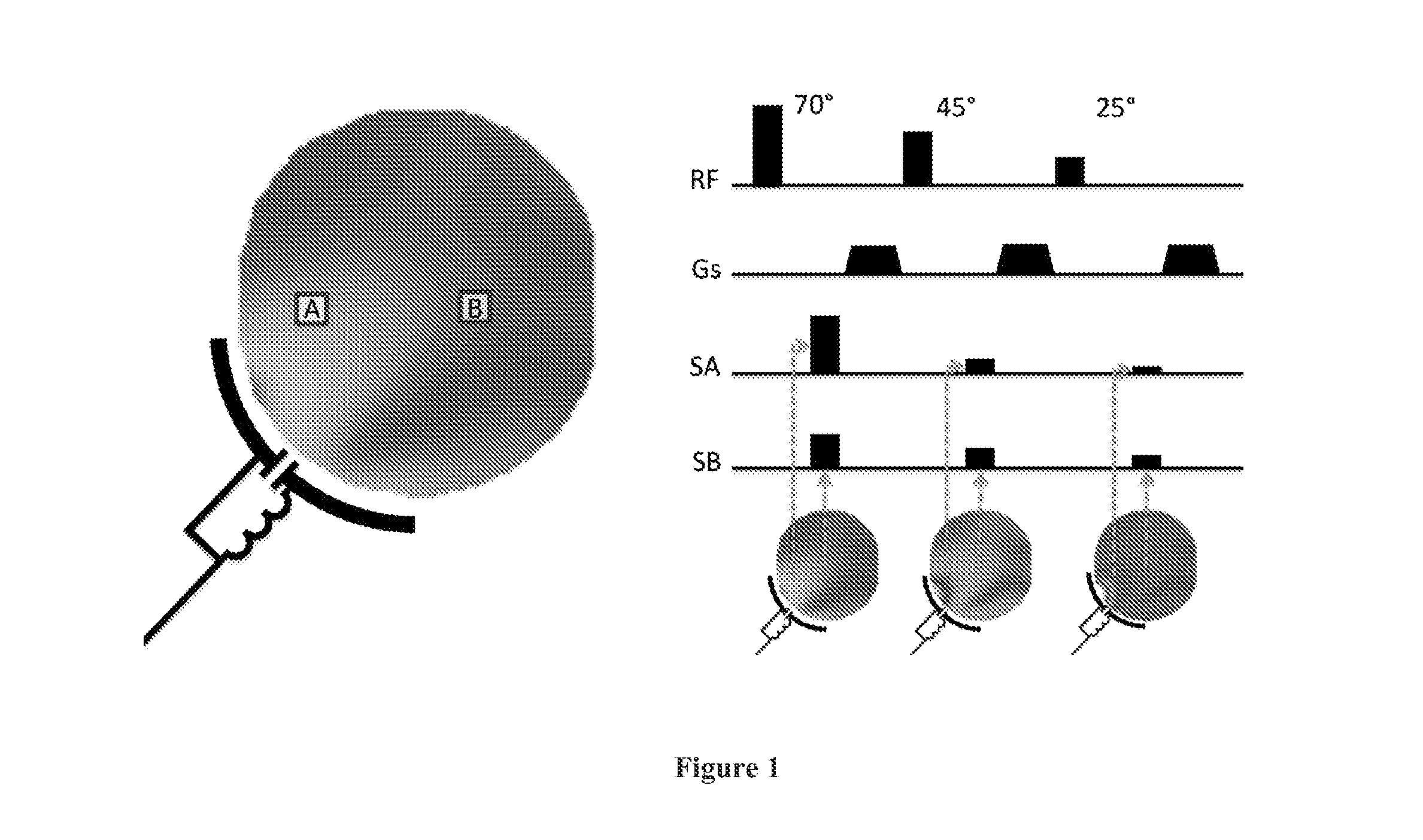
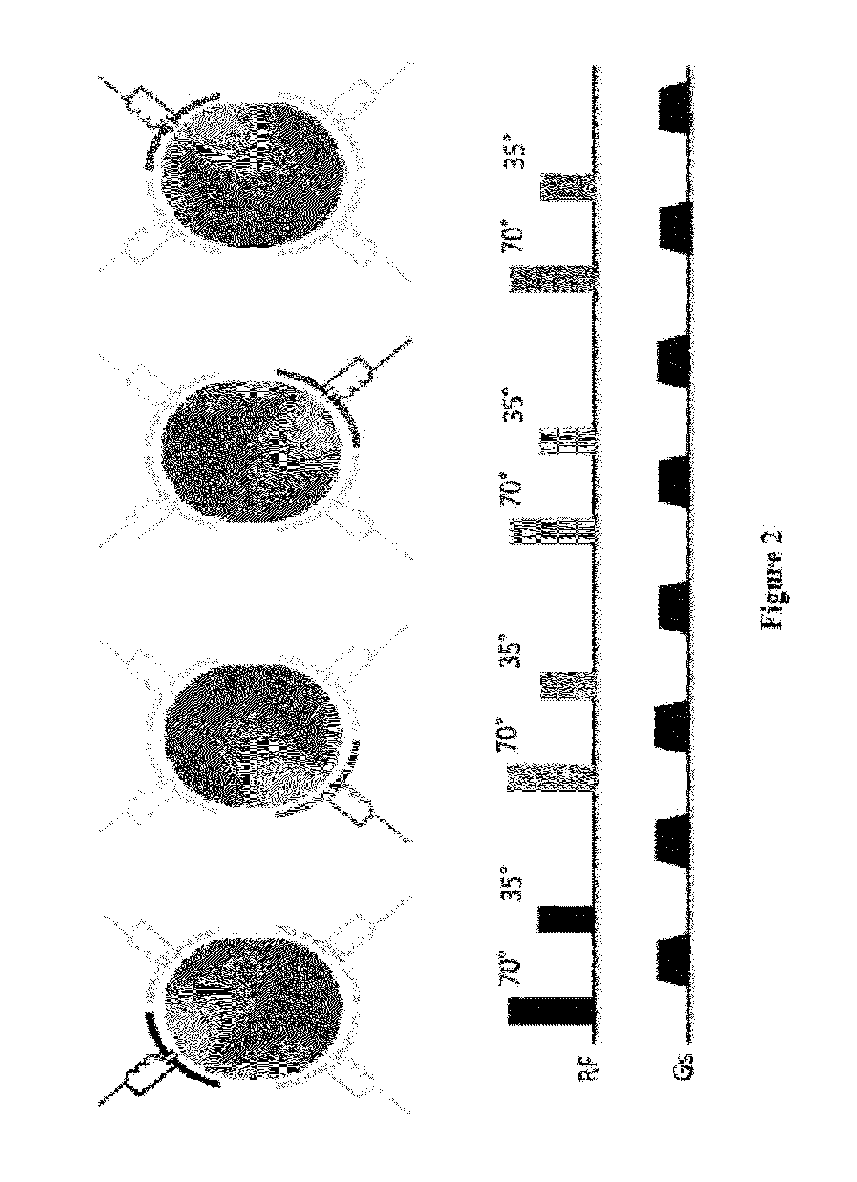
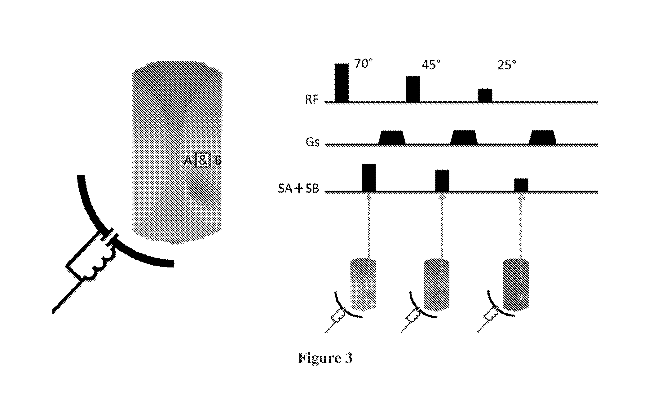
A general framework is for signal encoding in MRF that enables simultaneous transmit and receive encoding to accelerate the acquistion process, or improve the fidelity of the final image / parameter-map per unit scan time. The proposed method and systems capitalize on the distinct spatial variations in the sensitivity profile of each transmit-coil to reduce the acquistion time, and / or improve the fidelity of the final parameter-map per unit time.

Description

CROSS-REFERENCE TO RELATED APPLICATIONS[0001]This application claims priority to U.S. Provisional Application No. 61 / 904,716, filed Nov. 15, 2013, entitled SELF-CALIBRATING PARALLEL TRANSMISSION BY SPIN DYNAMIC FINGERPRINTING, reference of which is hereby incorporated in its entirety.FIELD OF THE INVENTION[0002]The present invention generally relates to magnetic resonance imaging.BACKGROUND OF THE INVENTION[0003]Magnetic Resonance Fingerprinting (MRF), a technique recently introduced by Ma, et al., 2013, represents a paradigm shift for Magnetic Resonance Imaging (MRI). In contrast to conventional imaging strategies, where the desired image is directly encoded in the frequency domain (Bernstein, et al., 2004), in MRF a parameter map is constructed from a time-series of highly under-sampled images. Although none of the individual snap-shots in a MRF experiment yields an accurate anatomical image, the complete set captures the time dependent spin evolution. When a suitably optimized MR...

Claims


Application Information

Patent Timeline
IPC IPC(8): G01R33/561G01R33/483G01R33/24G01R33/48A61B5/055G01R33/565
CPCG01R33/5612A61B5/055G01R33/56545G01R33/246G01R33/4828G01R33/4835G01R33/50G01R33/5602G01R33/5608
Inventor CLOOS, MARTIJN ANTON HENDRIK
Owner NEW YORK UNIV
Learn More