Medical devices and methods for creating bubbles

a medical device and bubble technology, applied in the field of medical devices configured to generate bubbles, can solve the problems of affecting the flow of blood to tissues and organs to which it is supplied, the lungs are still growing and not yet ready to receive blood, and the risk of clots that bypass the lungs and reach the left heart is heightened, so as to achieve the effect of being seen easily

Inactive Publication Date: 2016-10-06
MEDTRICK INC
View PDF9 Cites 7 Cited by
  • Summary
  • Abstract
  • Description
  • Claims
  • Application Information

AI Technical Summary

Benefits of technology

[0009]Imaging techniques such as Trans Thoracic Echocardiography (“TTE”) and Trans Esophageal Echocardiography (“TEE”) can be used for detection of PFO and similar conditions. For example, the heart can be imaged using ultrasound while a mixture of air and agitated saline (for example, 9 ml saline and 1 ml of air), including bubbles of the air, is injected through a patient's Intra-Venous line (“IV”). The mixture of bubbles and liquid can be agitated, producing a cloudy substance. When the mixture of air and saline enters the right side of the heart, an ultrasound image of the right atrium and the right ventricle can show white brightness therein, caused by the bubbles. Normally, the left heart would appear dark due to absence of microbubbles, as depicted in FIG. 3. However, when a PFO is present, some bubbles may flow from the right atrium to the left atrium, and can be visualized on the left side of the heart, for example in the ultrasound image, as depicted in FIG. 4. Sometimes the presence of a PFO is clear, and can be seen easily on the ultrasound monitor. In other cases a Valsalva maneuver can be used, under which pressure conditions between the left and right atria are changed for a short period of time with the help of the patient's cooperation.
[0011]While the substance is being mixed, an Apical Four Chamber Image of the heart is captured with the ultrasound machine. A recording length of the clip is set to, for example, 15-20 beats. Because the bubbles can quickly dissipate, both the preparation and pushing of cloudy mix of agitated saline and air bubbles, and capturing ultrasound images should be done simultaneously. When the cloudiness of agitated saline and bubbles is appropriate, the following steps are performed rapidly and skillfully in such a way that there is minimal loss of time, to prevent loss of agitation and disappearance of bubbles prior to injection into the IV:
[0018]In an embodiment, a syringe can create as a cloudy mix of agitated saline and air bubbles to assist in diagnosing PFO or ASD in the heart, or shunting in the vascular system. The device uses three chambers to produce a cloudy mix. A first chamber holds saline solution, a second chamber holds air, and mixing with agitation of saline solution and air bubbles occurs in a third camber. This third chamber can be configured with various types of geometric structures that assist in agitation and mixing to produce a cloudy mix of agitated saline and air bubbles. The geometric structures may be one or more small holes to create bubbles. The geometric structures may also include porous material to produce air bubbles. This device can create the cloudy mix of agitated solution and air bubbles just prior to being injected into the patients IV, thus minimizing the destruction of bubbles and loss of agitation prior to entering the IV. Steps in other methods such as manually mixing the saline solution with air and switching three way stopcock to the correct port of the IV can be eliminated. Further, the device can produce a consistent mix upon pressing the plunger irrespective of the individual skills and tendencies of varying users. Even further, the test can be performed with less volume. For example, if a defect is detected with, for example, 4 mL of an available, there is no need to push the entire volume of 10 mL into the IV. Then, if for some reason additional imaging is desired, the remaining 6 mL can be injected immediately, without needing additional mixing or other procedures. This helps prevent unnecessary volume overload in the vascular system of the patient, by reducing the volume of fluid technicians use.
[0020]In a further embodiment, a device configured to create a mixture of gas bubbles in a fluid can include a first chamber and a second chamber. The first chamber can be configured to hold liquid, and the second chamber can be configured to hold gas. Further, a valve can separate the contents of the first and second chambers from mixing. The device can also include an output, in communication with the first and second chamber, such that the fluid and gas can flow through the output, out of the device. Small-scale geometric features can be included, that can produce gas bubbles as the liquid and gas flow from the first and second chambers and through the output. A plunger on the device can simultaneously force the liquid and gas past the valve to mix with each other, through the small-scale geometric features to produce gas bubbles, and through the output. The valve can prevent this mixing of the liquid and the gas prior to movement of the plunger.

Problems solved by technology

In a fetus, the lungs are still growing and not yet ready to receive blood for oxygenation.
Any clot that bypasses the lungs and reaches the left heart poses a great risk of interfering with the blood supply to tissues and organs to which it flows.
For example, when such a clot enters an artery in the brain it may cause a stroke.
Unfortunately, the technique depicted in FIG. 5 can have certain drawbacks.
For example, poor skill in creating the cloudy mix of agitated saline and air bubbles can cause a false-negative result.
This risk is further heightened by a lack of consistency in the procedure, as the quality of the bubbles and the speed with which they are injected is highly variable, not only with the technique of the operator(s), but also over time as the bubbles dissipate.
For example, different technicians may use varying ratios of air and saline solution, or may apply inconsistent amounts of pressure through the syringe.
Further, the entire mixture is typically used, because the bubbles only last for a short period of time.
Thus, if the results of the test are inconclusive, the test must be repeated in full, risking a volume overload to the patient's vascular system.

Method used


Image

  • Medical devices and methods for creating bubbles
  • Medical devices and methods for creating bubbles
  • Medical devices and methods for creating bubbles

Examples


Embodiment Construction

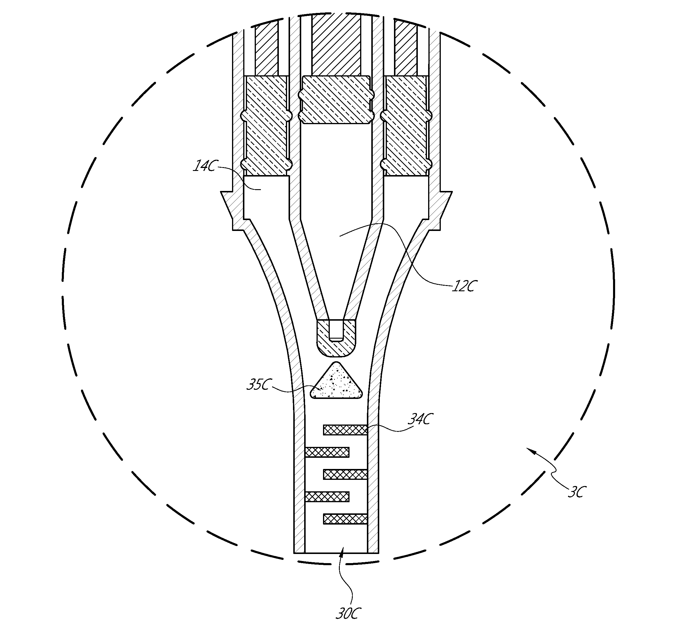
[0043]FIGS. 6, 6A-6D depict a device 1 that generates a bubble mixture that can optionally have a cloudy consistency. As discussed further below, the bubbles can be air bubbles formed in a saline solution. The bubbles can, in some embodiments, be “microbubbles”, small enough to show-up on a standard ultrasound machine in a medical setting, yet large enough to not pass through the lungs.

[0044]The device 1 can be a dedicated device that assists detecting a PFO, ASDs in the heart, or abnormal shunting in the vascular system. However, other applications are also possible, such as for detecting other features or use with other animals. As another example, the device can assist in the placement of a catheter at an appropriate place during pericardiocentesis, such as by injecting a mixture that can be imaged to indicate the location of a needle and / or catheter. Further, although the device 1 can be a medical device (and thus can be sterilized and otherwise made suitable for medical use), t...


PUM


Abstract

A dedicated device for detection of vascular shunts can include a first chamber, a second chamber, and a third chamber. The first chamber can be configured to hold liquid, the second chamber to hold gas, and the third chamber can be in communication with the first and second chambers. The third chamber can include small-scale geometric features configured to produce gas bubbles as liquid from the first chamber and gas from the second chamber simultaneously flow into the third chamber. The device can also include a device opening in communication with the third chamber such that a mixture of liquid and gas bubbles can flow out of the device opening. The device can also include a plunger configured to force the liquid and the gas simultaneously from the first and second chambers, through the third chamber to mix with each other and produce bubbles, and further through the device opening.

Description

PRIORITY INFORMATION[0001]This application claims priority benefit under 35 U.S.C. §119(e) to U.S. Provisional Patent Application Ser. No. 62 / 296,434 filed 17 Feb. 2016 and entitled “MEDICAL DEVICES AND METHODS FOR CREATING BUBBLES”; and U.S. Provisional Patent Application Ser. No. 62 / 178,084, filed 31 Mar. 2015 and entitled “Dedicated device created to perform bubble study, to detect presence of patent foramen ovale (PFO) or atrial septal defect (ASD) in the heart. Given name to the device is ‘B-Shoot’”, the entirety of each hereby expressly incorporated by reference herein.BACKGROUND[0002]1. Field[0003]This application relates to medical devices configured to generate bubbles. Such devices may be particularly useful for cardiovascular procedures, such as to detect the presence of Patent Foramen Ovale (“PFO”), Atrial Septal Defects (“ASD”), shunts in the heart, or other septal defects.[0004]2. Description of the Related Art[0005]The normal human heart, depicted in FIG. 1, can act a...

Claims


Application Information

Patent Timeline
Patent Type & Authority Applications(United States)
IPC IPC(8): A61M5/315A61M5/00A61M5/168A61M5/19A61M25/01A61M13/00A61B8/08
CPCA61M5/31596A61M13/003A61M5/007A61M5/315A61B8/0883A61M5/19A61M2210/125A61M25/0108A61M5/16881A61B8/0841A61B8/481A61M2005/006A61M5/002A61M16/06A61M16/10A61M2005/31598
Inventor SHARMA, AJAY
Owner MEDTRICK INC
Why Eureka
Try Eureka