Shell and tube heat exchanger

Inactive Publication Date: 2016-10-06
SEWON CELLONTECH
View PDF7 Cites 5 Cited by
  • Summary
  • Abstract
  • Description
  • Claims
  • Application Information

AI Technical Summary

Benefits of technology

[0021]A shell and tube heat exchanger in accordance with the present invention, under the condition that a tube joint member and a tube having the same diameter are inserted into each of tube insertion holes formed through tube sheets of a shell and tube heat exchanger and contact each other, a welding torch is inserted into the tube joint member to perform welding and, thus, the welding torch may easily approach targets for welding, and parti

Problems solved by technology

That is, in order to directly weld the outer sides of the tubes 10 to the shell side of the tube sheet 20 using the welding torch T, welding of tubes 10 located at the edge region of the tube sheet 20 is possible but, when other adjacent tubes 10 or other tubes 10 located at the central region of the tube sheet 20 are welded to the tube sheet 20, interference between the tube 10 and the tube 10 occurs and thus welding is difficult, welding efficiency is lowered and complete welding operation is difficult.
However, since welding heat of the welding touch T is not directly transmitted to the tube sheet lower end joint part 23 of the tube sheet 20 welded to the outer circumferen

Method used


Image

  • Shell and tube heat exchanger
  • Shell and tube heat exchanger
  • Shell and tube heat exchanger

Examples


Example

[0033]Hereinafter, with reference to the accompanying drawings, preferred embodiments of a shell and tube heat exchanger in accordance with the present invention will be described in detail.

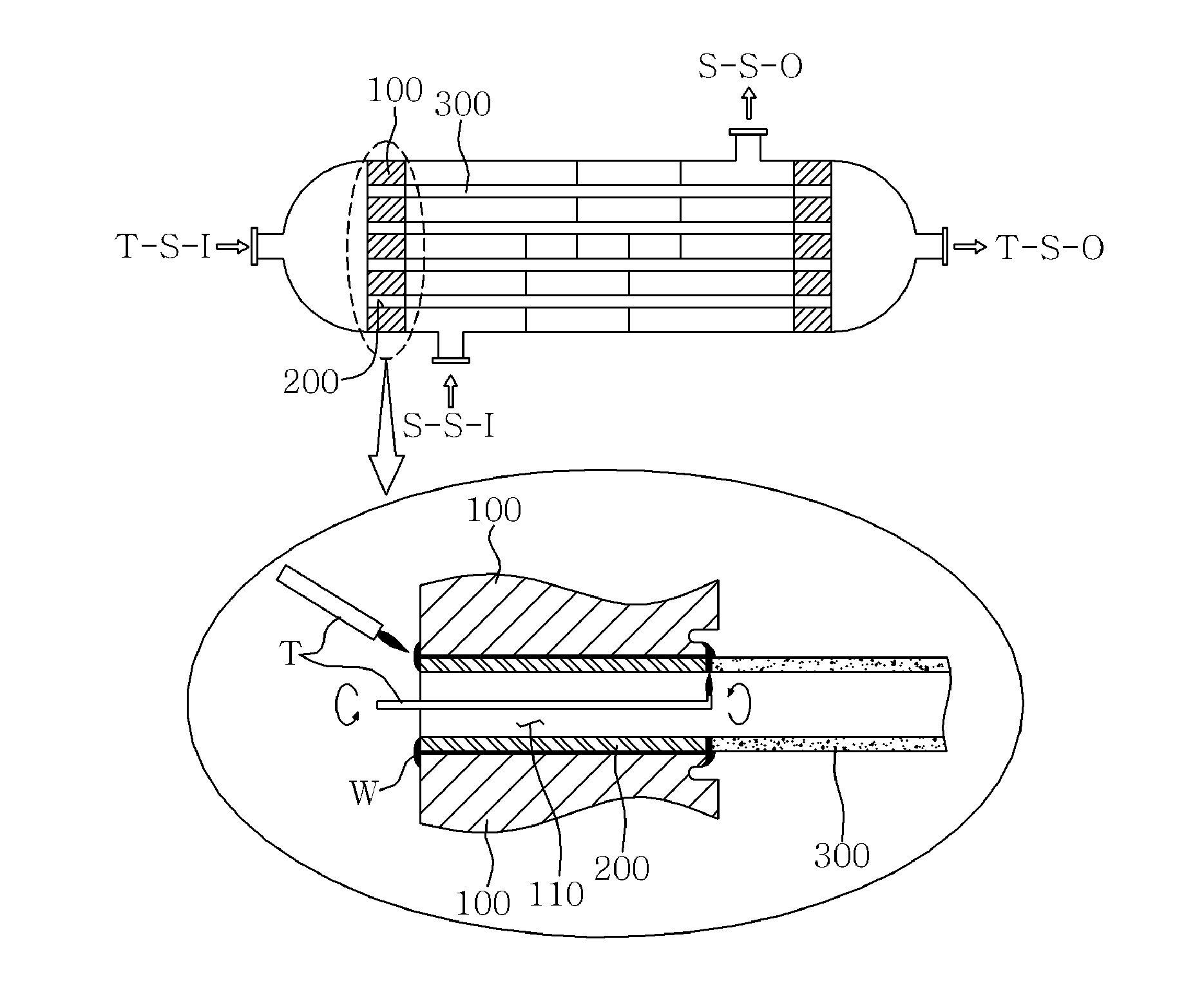
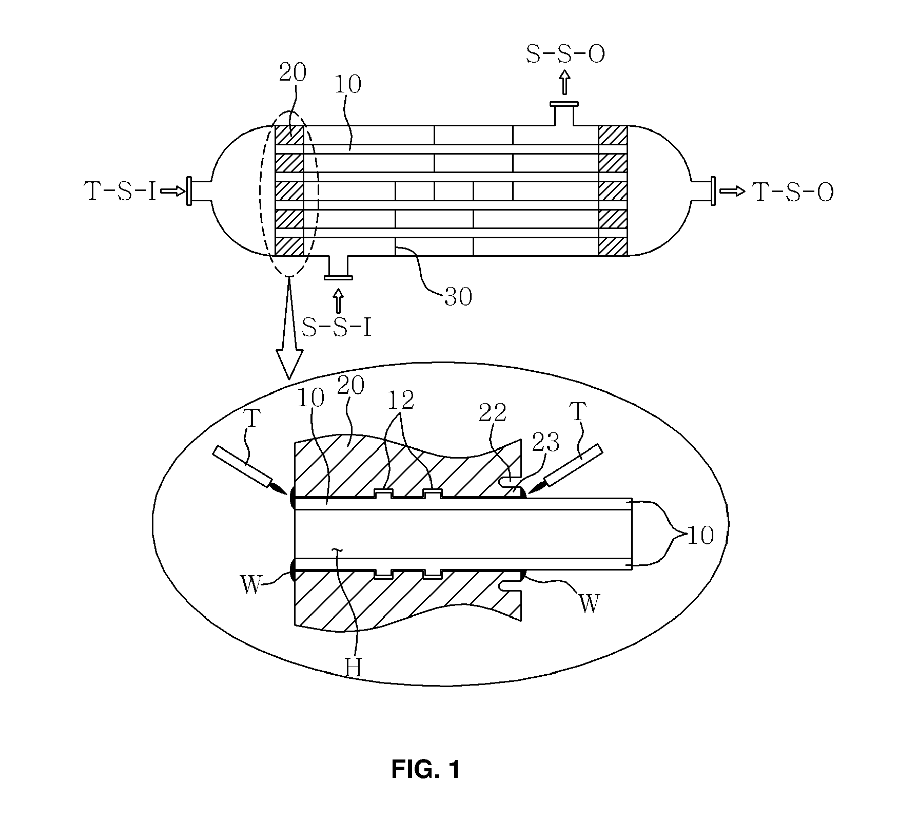
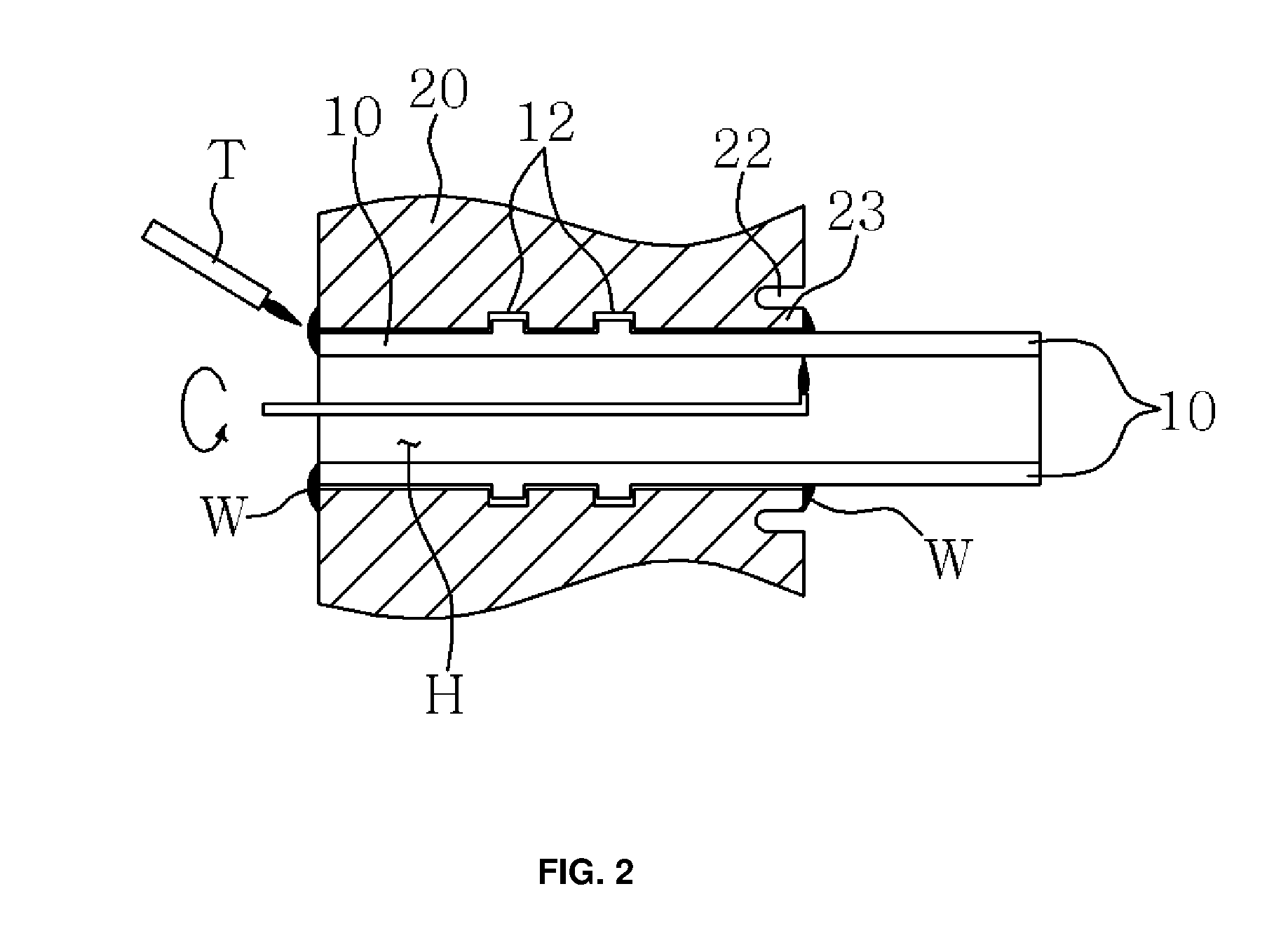
[0034]A shell and tube heat exchanger in accordance with the present invention, as exemplarily shown in FIG. 3, includes a shell 1 having a cylindrical body, a pair of tube sheets 100 installed to divide the inside of the shell 1 and provided with a plurality of tube insertion holes 110 so as to face each other, and a plurality of tubes 300 respectively welded to the tube insertion holes 110 facing each other to connect the tube sheets 100, and may further include tube joint members 200 and wire rings 400. The tube sheet 100 includes the tube insertion holes 110, tube sheet grooves 120 and joint parts 130, and the tube joint member 200 and the tube 300 are inserted into the tube insertion hole 110 of the tube sheet 100 and combined with to the tube sheet 100 by welding.

[0035]A shell and tube heat...


PUM

PropertyMeasurementUnit
Distanceaaaaaaaaaa

Abstract

A shell having a cylindrical body, a pair of tube sheets installed to divide the inside of the shell and provided with a plurality tube insertion holes formed therethrough so as to face each other, and a plurality of tubes respectively welded to the tube insertion holes facing each other to connect the tube sheets, and further including a plurality of tube joint members having the same diameter as that of the tubes and respectively inserted into the tube insertion holes of the tube sheets, and a plurality of ring wires manufactured by cutting a welding wire having a long length into pieces having a designated length and bending the pieces into a ring shape and inserted into the outer circumferences of both ends of the tubes, wherein ring-shaped tube sheet grooves spaced from the tube insertion holes by a designated distance in the outer circumferential surface are formed on each of facing surfaces of the tube sheets so as to form joint parts, both ends of the tubes are inserted into the tube insertion holes of the tube sheets facing each other such that both ends of the tubes contact one end of each of the tube joint members facing the ends of the tubes and are located within the recessed distance range of the tube sheet grooves, and the ends of the tubes together with the tube joint members and the joints are welded to the respective tube sheets by a welding torch inserted into each of the tube joint members using the ring wires as a filler metal.

Description

REFERENCE TO RELATED APPLICATIONS[0001]This application claims the priority benefit of Korean Patent Application No. 10-2015-0047765 filed on Apr. 3, 2015, the entire contents of which are incorporated herein by reference.FIELD OF THE INVENTION[0002]The present invention relates to a shell and tube heat exchanger in which different fluids are introduced into and discharged from a tube side and a shell side so as to exchange heat with each other.BACKGROUND OF THE INVENTION[0003]A shell and tube heat exchanger includes two tube sheets and a plurality of tubes connecting the tube sheets and is configured to be enclosed by a cylindrical body, i.e., a shell. The shell and tube heat exchanger is used in various types of heat exchange, such as heating, cooling, condensation, evaporation, etc.[0004]In general, a shell and tube heat exchanger is configured such that different fluids are introduced into and discharged from a tube side and a shell side and the fluid at the tube side and the fl...

Claims


Application Information

Patent Timeline
IPC IPC(8): B23K1/00F28F19/00F28D7/16
CPCB23K1/0012F28F19/00F28D7/1607B23K31/02F28D7/16F28F9/185F28F2275/06B23K3/021B23K3/0623B23K35/0222B23K2101/14F28F9/18B23K9/0288F28F9/013
Inventor YOO, YONG HYUNLEE, KANG JUNPARK, SHIN GHUJU, JEONG CHEOLJI, YOUNG SIKBAE, DEUNG SEOB
Owner SEWON CELLONTECH
Why Eureka
Try Eureka