Method and magnetic resonance apparatus for speed-compensated diffusion-based diffusion imaging

a magnetic resonance apparatus and diffusion imaging technology, applied in the direction of magnetic measurements, measuring devices, instruments, etc., can solve the problems of signal loss, error in the evaluation of diffusion maps, overestimation of apparent diffusion coefficient (adc), etc., and achieve the effect of shorter time and higher diffusion sensitivity

Active Publication Date: 2016-10-06
SIEMENS HEALTHCARE GMBH
View PDF8 Cites 9 Cited by
  • Summary
  • Abstract
  • Description
  • Claims
  • Application Information

AI Technical Summary

Benefits of technology

The invention is about a way to use a magnetic resonance imaging system to get better and faster magnetic resonance images of a person or object. It does this by using a special technique that compensates for the velocity of the molecules in the object being examined. This makes it easier to get high-quality images faster than usual.

Problems solved by technology

Such distortion can result in errors in the evaluated diffusion maps.
However, when this kind of pulse sequence is used for diffusion-weighted imaging of the liver and heart, signal losses occur which are attributable to the motion of the heart.
These signal losses increase with the diffusion weighting and hence result in an overestimation of the apparent diffusion coefficient (ADC).
This is a problem when the ADC value is used as a discriminator between benign and malignant lesions.
The main disadvantage of this velocity-compensated sequence is that the bipolar gradients in this sequence have significantly less diffusion sensitivity than the Stejskal-Tanner sequence.
This results in a prolongation of the echo time of the sequence and hence, due to the inherent T2 decay of the tissue, to a deterioration of the signal / noise ratio (SNR), which can only be compensated by a significantly longer measuring time.
Symmetrization of the two times (for example due to the non-acquisition of the earlier lines of an EPI readout train) can entail significant problems up to complete signal loss if the echo is shifted in the k-space due to macroscopic motion during diffusion sensitization in the non-acquired range.

Method used


Image

  • Method and magnetic resonance apparatus for speed-compensated diffusion-based diffusion imaging
  • Method and magnetic resonance apparatus for speed-compensated diffusion-based diffusion imaging
  • Method and magnetic resonance apparatus for speed-compensated diffusion-based diffusion imaging

Examples


Embodiment Construction

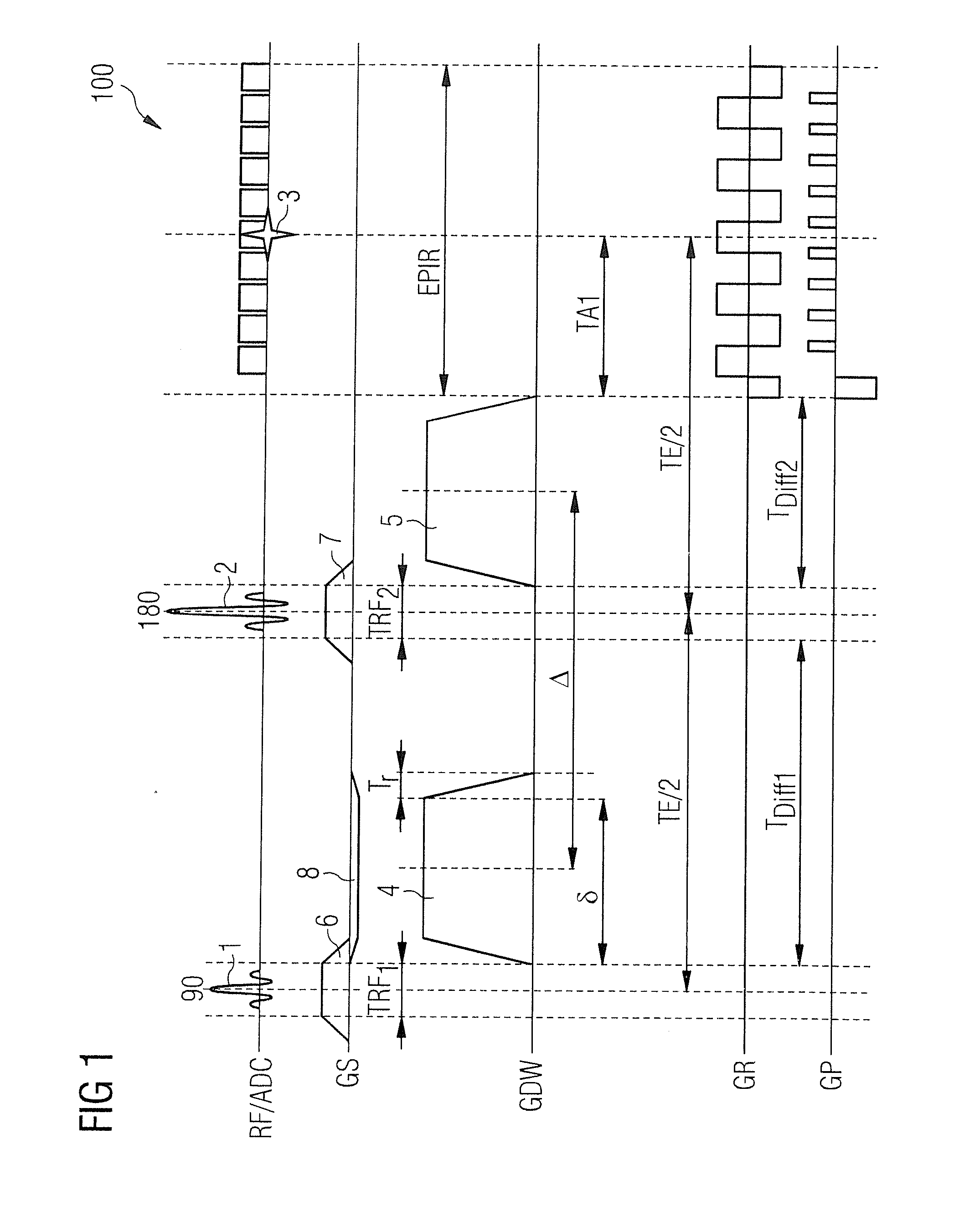
[0062]FIG. 1 shows a Stejskal-Tanner sequence. This is by far the most important diffusion-weighted pulse sequence in the prior art. The first line of the graph, which is identified with RD / ADC, shows an RF excitation pulse 1, which is switched as the start of a pulse sequence simultaneously with a slice selection gradient 6 (see second line GS) and an RF refocusing pulse 2, which is switched between two diffusion contrast gradient pulses 4, 5 (see third line GDW) and with which a slice selection gradient 7 is also switched simultaneously (see second line GS). The gradient pulses 4, 5 have the same polarity and as a rule the same amplitude and duration. The RF refocusing pulse 2 forms a spin echo 3 (see first line), which, in the example shown, is read out with an EPI echo readout train EPIR comprising a plurality of readout windows. Furthermore, in the graph in FIG. 1, the second line from the bottom shows a gradient sequence GR in the readout direction (frequency encoding directio...


PUM


Abstract

In a magnetic resonance imaging system and operating method for generating magnetic resonance image data of an object under examination, in order to acquire magnetic resonance raw data, an operating sequence is determined that has an excitation wherein an RF excitation pulse is radiated, and a readout procedure for receiving RF signals. In addition, a diffusion contrast gradient pulse sequence is generated that includes an uneven number of 2n+1 diffusion contrast gradient pulses switched in chronological succession, with the sum of the zero gradient moments of the diffusion contrast gradient pulses having the value zero and the sum of the first gradient moments of the diffusion contrast gradient pulses having the value zero. An RF refocusing pulse is switched between two of the diffusion contrast gradient pulses.

Description

BACKGROUND OF THE INVENTION[0001]1. Field of the Invention[0002]The invention concerns a method for operating a magnetic resonance imaging system for generating magnetic resonance image data of an object under examination, with which magnetic resonance raw data are acquired. The invention also concerns an actuation sequence for actuating a magnetic resonance imaging system. In addition, the invention concerns a magnetic resonance imaging system designed to implement such a method.[0003]2. Description of the Prior Art[0004]For the generation of magnetic resonance recordings, the body to be examined is exposed to a relatively high basic magnetic field of for example, 1.5 tesla, 3 tesla, or in newer high magnetic field systems, even 7 tesla and more. Then a suitable antenna device emits a radio-frequency excitation causing the nuclear spins of specific atoms that are excited to resonance by this radio-frequency field in the magnetic field to be flipped by a specific flip angle relative...

Claims


Application Information

Patent Timeline
IPC IPC(8): G01R33/565G01R33/561G01R33/563
CPCG01R33/56509G01R33/5617G01R33/5616G01R33/56341A61B5/055G01R33/561G01R33/20G01R33/4608G01R33/4616G01R33/4625G01R33/48
Inventor STEMMER, ALTO
Owner SIEMENS HEALTHCARE GMBH
Why Eureka
Try Eureka