Laser radar device

a laser radar and laser technology, applied in the direction of instruments, lasers using reradiation, semiconductor lasers, etc., can solve the problem of limited transmission light peak power, and achieve the effect of simple and low-cost configuration

Inactive Publication Date: 2016-10-06
MITSUBISHI ELECTRIC CORP
View PDF0 Cites 41 Cited by
  • Summary
  • Abstract
  • Description
  • Claims
  • Application Information

AI Technical Summary

Benefits of technology

[0013]Because the laser radar device according to the present invention is configured as above, the laser radar device can simultaneously perform measurements on many sight line directions with a simple and low-cost configuration and without using a scanner device that mechanically drives a component.

Problems solved by technology

Further, in a coherent laser radar device in which optical fibers are used as transmission paths for transmission lights (laser lights), the peak powers of the transmission lights are limited by a nonlinear optical effect which occurs in optical fibers and which is called stimulated Brillouin scattering.

Method used


Image

  • Laser radar device
  • Laser radar device
  • Laser radar device

Examples


embodiment 1

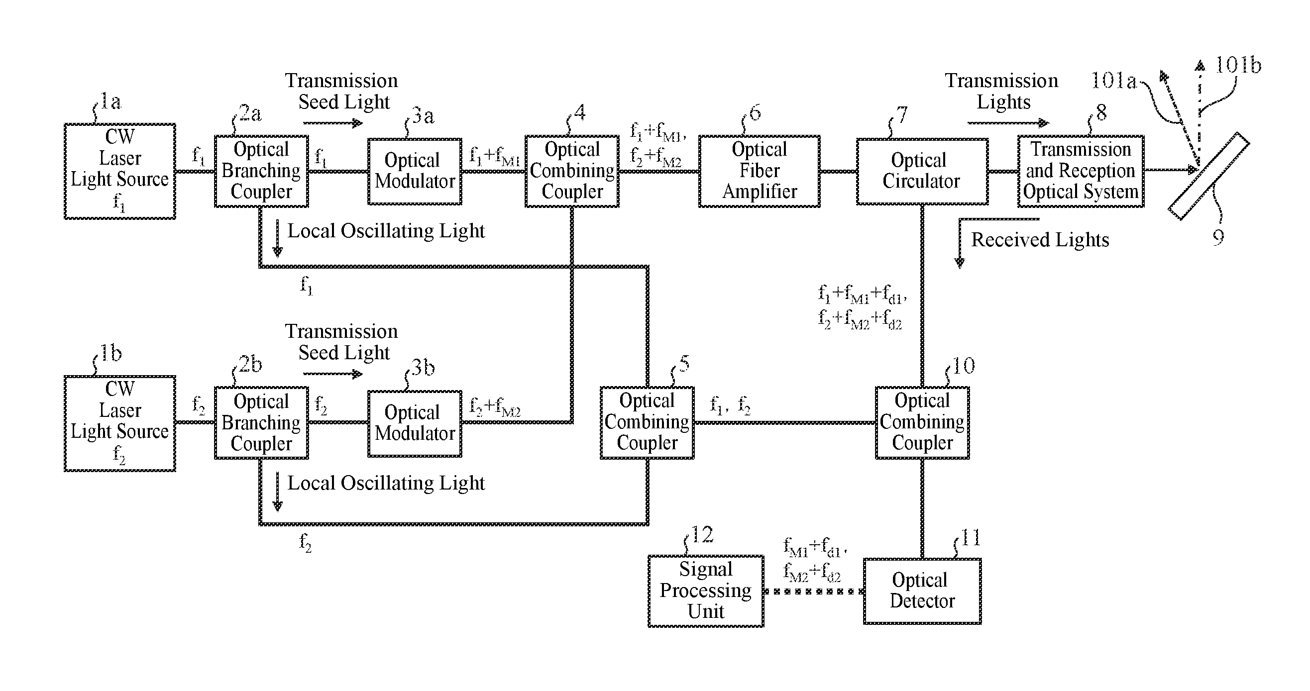
[0026]FIG. 1 is a diagram showing the configuration of a laser radar device according to Embodiment 1 of the present invention.

[0027]The laser radar device is a coherent Doppler lidar device that measures wind speeds by radiating a laser light into the air, receiving a scattered light from aerosols (particles such as dust suspended in the air), and detecting the Doppler shift of this scattered light. This laser radar device is comprised of a plurality of CW laser light sources (reference light sources) 1, a plurality of optical branching couplers 2, a plurality of optical modulators 3, an optical combining coupler (a first optical combiner) 4, an optical combining coupler (a second optical combiner) 5, an optical fiber amplifier 6, an optical circulator 7, a transmission and reception optical system 8, a diffraction grating (a dispersing element) 9, an optical combining coupler (a third optical combiner) 10, an optical detector 11 and a signal processing unit (an information extract...

embodiment 2

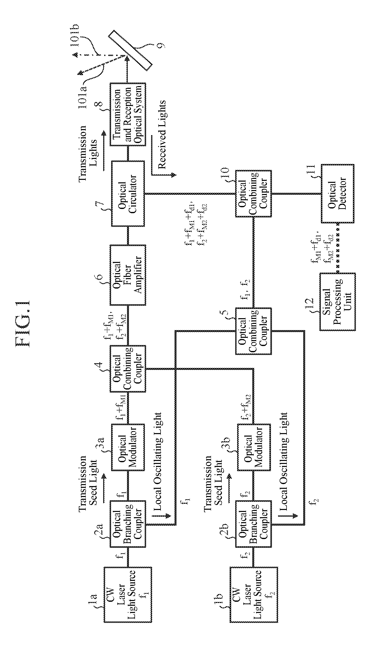
[0092]FIG. 2 is a diagram showing the configuration of a laser radar device according to Embodiment 2 of the present invention. The laser radar device according to Embodiment 2 shown in FIG. 2 is a one in which the CW laser light sources 1a and 1b of the laser radar device according to Embodiment 1 shown in FIG. 1 are replaced by CW laser light sources 13a and 13b. The other components are the same as those of Embodiment 1 and are designated by the same reference character strings, and only a different portion will be explained hereafter.

[0093]The CW laser light source 13a can vary its oscillating frequency within a range from f1 to f1′, and oscillates a CW laser light having a set specific frequency. The CW laser light oscillated by this CW laser light source 13a is coupled to an optical fiber, and is outputted to an optical branching coupler 2a.

[0094]The CW laser light source 13b can vary its oscillating frequency within a range from f2 to f2′, and oscillates a CW laser light hav...

embodiment 3

[0106]FIG. 3 is a diagram showing the configuration of a laser radar device according to Embodiment 3 of the present invention. The laser radar device according to Embodiment 3 shown in FIG. 3 is a one in which the optical branching coupler 2b, the optical modulator 3b and the optical combining couplers 4 and 5 are removed from the laser radar device according to Embodiment 1 shown in FIG. 1, and driving circuits 14a and 14b , a controller 15 and an optical combining coupler 16 are added. The other components are the same as those of Embodiment 1 and are designated by the same reference character strings, and only a different portion will be explained hereafter.

[0107]The driving circuit 14a is disposed while being brought into correspondence with a CW laser light source 1a, and operates the CW laser light source 1a.

[0108]The driving circuit 14b is disposed while being brought into correspondence with a CW laser light source 1b, and operates the CW laser light source 1b.

[0109]The c...


PUM


Abstract

Disclosed is a laser radar device including optical branching couplers each of that branches a laser light oscillated, optical modulators each of that modulates a laser light after being branched, an optical combining coupler that combines laser lights modulated by the optical modulators, an optical combining coupler that combines other laser lights after being branched, an optical system that emits a composite light from the optical combining coupler, and receives lights scattered by a target, an optical combining coupler that combines the scattered lights and a composite light from the optical combining coupler, an optical detector that detects beat signals from a composite light from the optical combining coupler, a signal processing unit that extracts information about the target from the beat signals, and a diffraction grating that emits a light incident thereupon toward a specific direction according to the angle and the frequency of the incident light.

Description

FIELD OF THE INVENTION[0001]The present invention relates to a laser radar device that emits a laser light into the air, receives a scattered light of that laser light which is scattered by a target, and extracts information about the target from the scattered light.BACKGROUND OF THE INVENTION[0002]As a conventional laser radar device, there has been provided a coherent laser radar device that pulses a transmission light by using, as an optical modulator, an acousto-optic (AO) element which is pulse-driven (for example, refer to nonpatent reference 1).[0003]Further, in a coherent laser radar device in which optical fibers are used as transmission paths for transmission lights (laser lights), the peak powers of the transmission lights are limited by a nonlinear optical effect which occurs in optical fibers and which is called stimulated Brillouin scattering. To solve this problem, a method of performing a measurement with a high S / N ratio by increasing the transmission power by using...

Claims


Application Information

Patent Timeline
Patent Type & Authority Applications(United States)
IPC IPC(8): G01S7/481G01S17/95H01S3/00H01S3/067H01S3/30G01S17/58H01S3/23
CPCG01S7/4815G01S17/58G01S17/95H01S3/005H01S3/06754H01S3/302H01S3/0085H01S3/2391H01S5/0617Y02A90/10
Inventor SAKIMURA, TAKESHIYANAGISAWA, TAKAYUKIMIWA, YOSHICHIKA
Owner MITSUBISHI ELECTRIC CORP
Why Eureka
Try Eureka