Display Apparatus

a technology of display apparatus and display screen, which is applied in the field of display screen, can solve the problems of increasing the radiation of electromagnetic wave noise, generating harmonics, and becoming noise currents, and achieve the effect of appropriate suppression of electromagnetic wave nois

Inactive Publication Date: 2016-10-06
SAKAI DISPLAY PROD
View PDF4 Cites 1 Cited by
  • Summary
  • Abstract
  • Description
  • Claims
  • Application Information

AI Technical Summary

Benefits of technology

[0008]However, in the configuration of interposing the washers between the bezel or chassis and the screws, since it is only possible to select whether the washer is interposed for each screw, there is a limit to an effect of suppressing the EMI. In addition, due to interposing the washer, a fastening strength by the screws may be decreased. Further, since head portions of the washer and the screw protrude from an outer surface of the bezel or the chassis, a length of protrusion portions (projections) becomes longer.
[0011]According to the embodiment of the present invention, the holding member which holds the display panel having the display region on one surface thereof from the other surface side and the frame member which abuts the peripheral edge part of the one surface of the display panel are fastened by the plurality of fastening members. As the plurality of fastening members, the plurality of types of fastening members having different electrical resistance values from each other are used in combination with each other. A resonance frequency in a housing formed by fastening the holding member and the frame member by the fastening members is affected by not only electrical resistance values of the holding member and the frame member, but also electrical resistance values of the fastening members. Thereby, by fastening the holding member and the frame member by the plurality of fastening members having different electrical resistance values from each other, it is possible to configure in such a way that the resonance frequency of the housing does not coincide with a frequency of an electromagnetic wave noise radiated from the display apparatus. Generally, an electric equipment such as the display apparatus has different resonance frequencies depending on components (a printed board, and the like) housed in the housing, a combination of the respective components, and an arrangement position thereof. Also, in such the electric equipment, by selecting the electrical resistance values of the respective fastening members to be used, the resonance frequency can be finely adjusted, and an adjustable range is widened. Thereby, also in the display apparatus having any configuration, it is possible to suppress an EMI by using the fastening members suitable for each display apparatus.
[0015]According to the preferred embodiment of the present invention, the holding member and the frame member are fastened by the fastening members at the plurality of fastening locations along the frame member. In addition, the type of the fastening members to be fastened at each location on the one end side of the frame member is different from the type of the fastening members to be fastened at the other locations. By such the configuration, in a display apparatus having an electromagnetic wave noise radiated from the one end side of the frame member larger than the electromagnetic wave noise radiated from the other end side, it is possible to achieve the configuration capable of appropriately suppressing the electromagnetic wave noise (EMI).
[0017]According to the preferred embodiment of the present invention, in the display apparatus in which the holding member and the frame member are made of the conductive member, it is possible to achieve the configuration capable of appropriately suppressing the EMI.
[0018]According to one embodiment of the present invention, by changing the electrical resistance values of the respective fastening members which fasten the holding member and the frame member, it is possible to adjust the resonance frequency in the housing, and suppress the EMI. In addition, as compared to the configuration of interposing the washers between the bezel (frame member) or chassis (holding member) and the screws (fastening members), it is possible to obtain an effect in which a decrease in the fastening strength due to the fastening members does not occur, and locations where the fastening members protrude from the frame member or the holding member can be formed to be short by as much as a level with no washer interposed therebetween.

Problems solved by technology

When the signal is transmitted at a high speed by wiring patterns formed on the printed board, harmonics are generated, which become a noise current to be leaked out from the printed board (wiring patterns).
In addition, when the noise current has reached the bezel or the chassis, an electromagnetic wave noise is radiated to an outside of the display apparatus through the bezel or the chassis serving as an antenna.
In this case, when a frequency of the electromagnetic wave noise and a resonance frequency of the bezel or the chassis coincide with each other, an amount of radiation of the electromagnetic wave noise is increased.
However, in the configuration of interposing the washers between the bezel or chassis and the screws, since it is only possible to select whether the washer is interposed for each screw, there is a limit to an effect of suppressing the EMI.

Method used


Image

  • Display Apparatus
  • Display Apparatus
  • Display Apparatus

Examples


Embodiment Construction

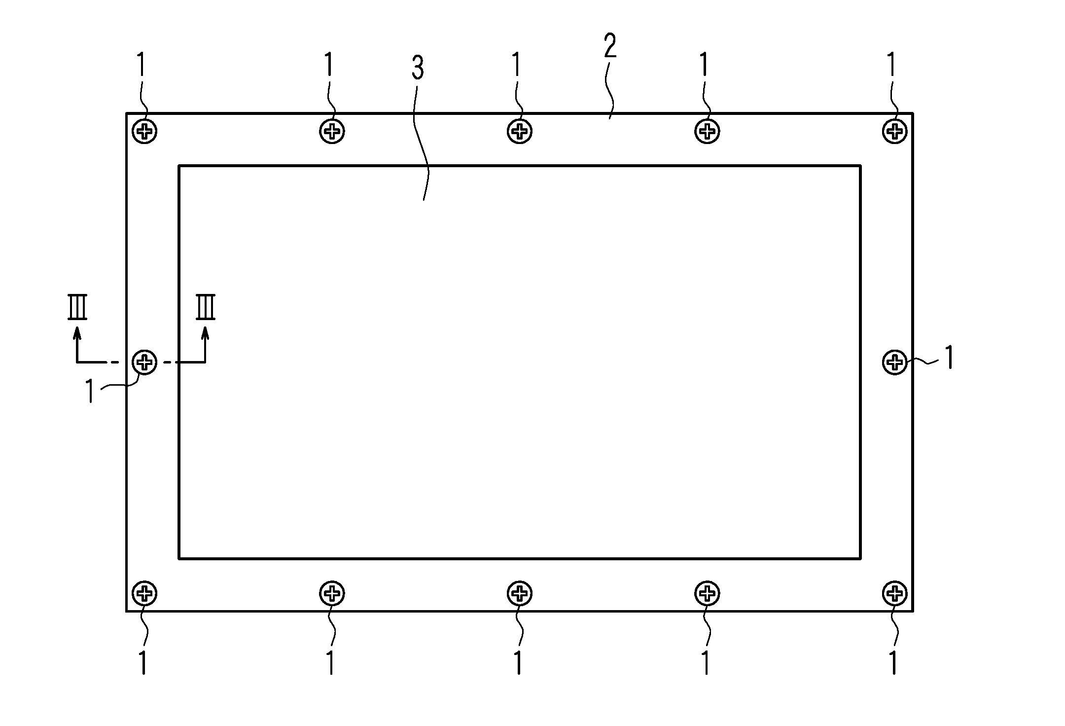
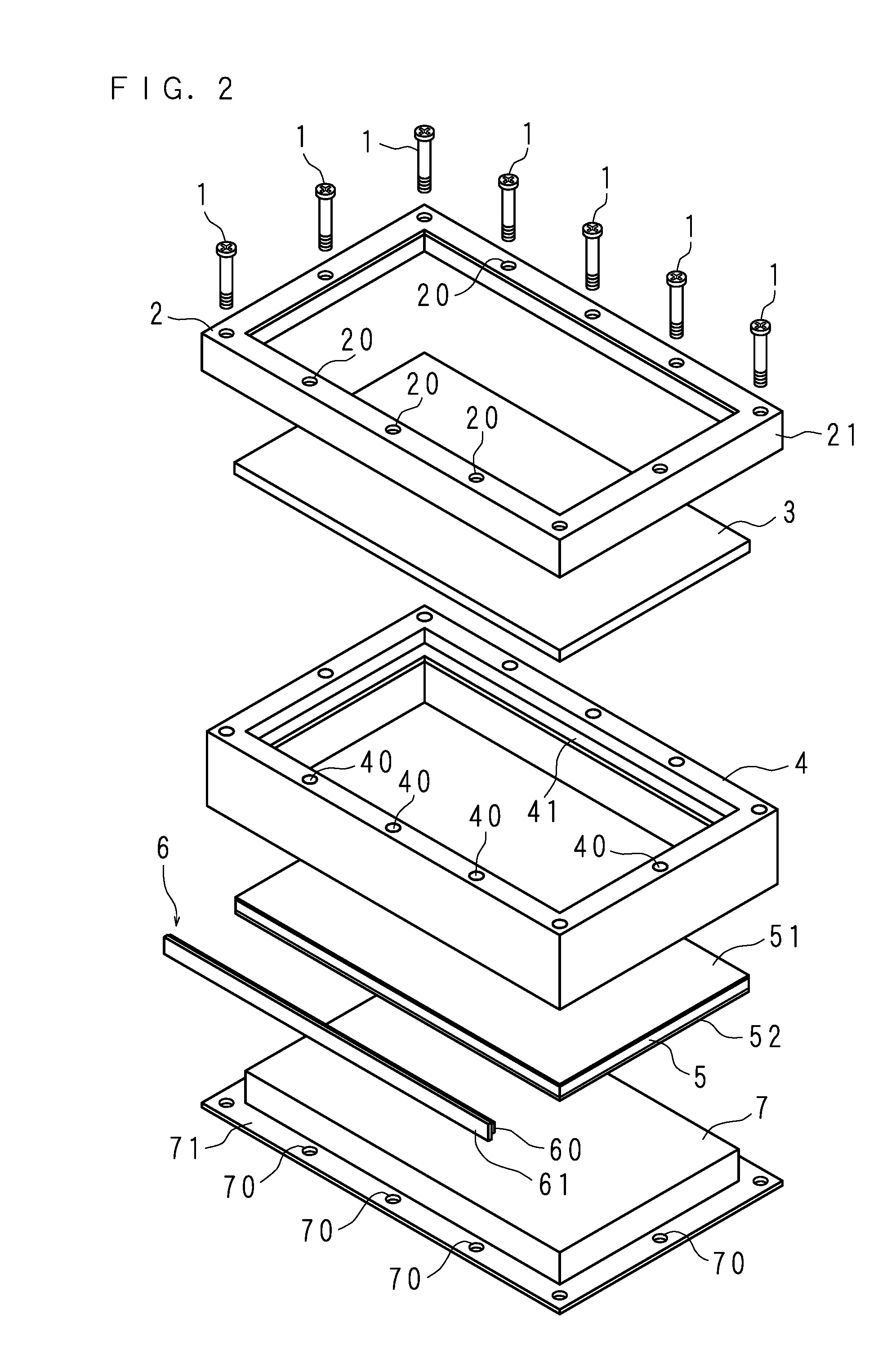
[0034]Hereinafter, a display apparatus according to the present invention will be described in detail with reference to the accompanying drawings illustrating the embodiments thereof. FIG. 1 is a front view of a display apparatus according to the embodiment, FIG. 2 is an exploded perspective view illustrating a configuration of major parts of the display apparatus according to the embodiment, and FIG. 3 is a cross-sectional view taken on line III-III of FIG. 1. As illustrated in FIG. 2, the display apparatus of the embodiment is formed in such a way that a bezel (frame member) 2, a liquid crystal panel (display panel) 3, a panel chassis 4, a light guide plate 5, a light source unit 6 and a backlight chassis (hereinafter, referred to as a BL chassis or a holding member) 7 are overlapped in this order, and fastened by a plurality of fastening members (screws) 1.

[0035]The bezel 2 is a rectangular frame member (conductive member) made of metal, and has a plate part 21 which vertically p...


PUM

PropertyMeasurementUnit
rotation angleaaaaaaaaaa
electrical resistanceaaaaaaaaaa
conductiveaaaaaaaaaa

Abstract

A bezel abutting a peripheral edge of a display region of a liquid crystal panel having the display region on one surface, and a BL chassis holding the liquid crystal panel from the other surface side of the liquid crystal panel are fastened to each other by a plurality of fastening members to form a housing. Each of the fastening members is selected from a plurality of types of the fastening members having different electrical resistance values for each fastening location so that a resonance frequency of the housing does not coincide with a frequency of the electromagnetic wave noise radiated from the housing.

Description

CROSS-REFERENCE TO RELATED APPLICATION[0001]This application is the national phase under 35 U.S.C. §371 of PCT International Application No. PCT / JP2013 / 081720 which has an International filing date of Nov. 26, 2013 and designated the United States of America.BACKGROUND[0002]1. Technical Field[0003]The present invention relates to a display apparatus in which a bezel abutting a peripheral edge of one surface of a display panel and a chassis holding the display panel from the other surface side are fastened to each other by screws.[0004]2. Description of Related Art[0005]Display apparatuses such as a liquid crystal display and a liquid crystal television have been widely distributed. The display apparatus includes a display panel having a display surface for displaying an image on one surface. In addition, the display apparatus has often a configuration in which a bezel abutting a peripheral edge of the display surface from the one surface side of the display panel and a chassis holdi...

Claims


Application Information

Patent Timeline
Patent Type & Authority Applications(United States)
IPC IPC(8): G02F1/1333
CPCG02F1/133308G02F2201/46G02F2001/133334G02F1/13332G02F1/133334
Inventor AIKAWA, YASUYUKI
Owner SAKAI DISPLAY PROD
Why Eureka
Try Eureka