Broadband antenna, multiband antenna unit and antenna array

a multi-band antenna and antenna array technology, applied in the field of broadband antennas, can solve the problems of cumbersome disclosure of antenna elements and considerable weight, and achieve the effects of reducing size, improving impedance characteristics, and maintaining or improving siz

Active Publication Date: 2016-10-06
KAELUS AB
View PDF1 Cites 17 Cited by
  • Summary
  • Abstract
  • Description
  • Claims
  • Application Information

AI Technical Summary

Benefits of technology

The patent discusses an antenna that solves issues with being too big and having poor impedance characteristics. The goal is to create a smaller antenna that works better.

Problems solved by technology

The above described references disclose complicated mechanical structures that require high complexity die-cast metal parts and therefore have considerable weight.
The disclosed antenna elements are also cumbersome due to its height and overall large size.

Method used


Image

  • Broadband antenna, multiband antenna unit and antenna array
  • Broadband antenna, multiband antenna unit and antenna array
  • Broadband antenna, multiband antenna unit and antenna array

Examples


Embodiment Construction

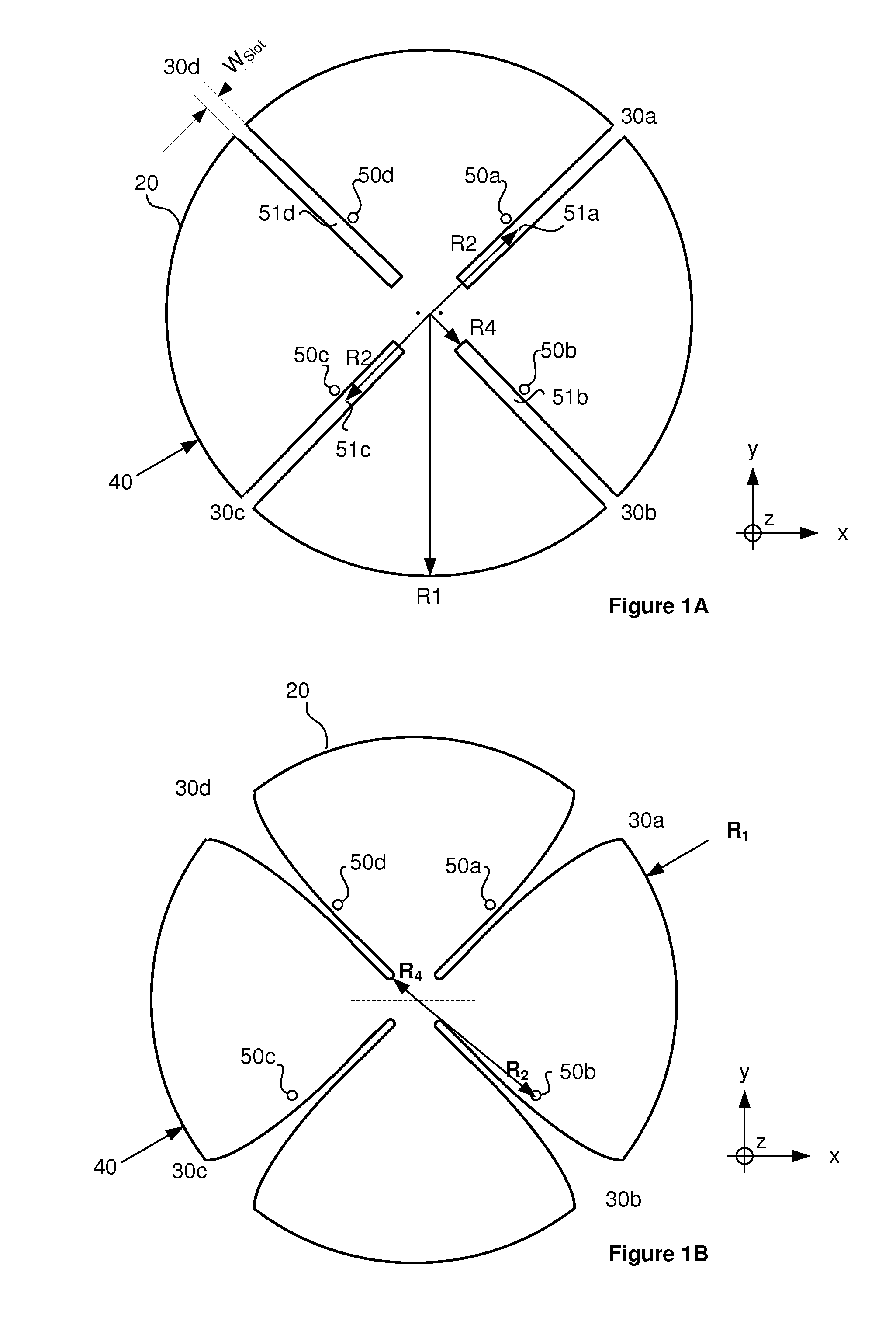
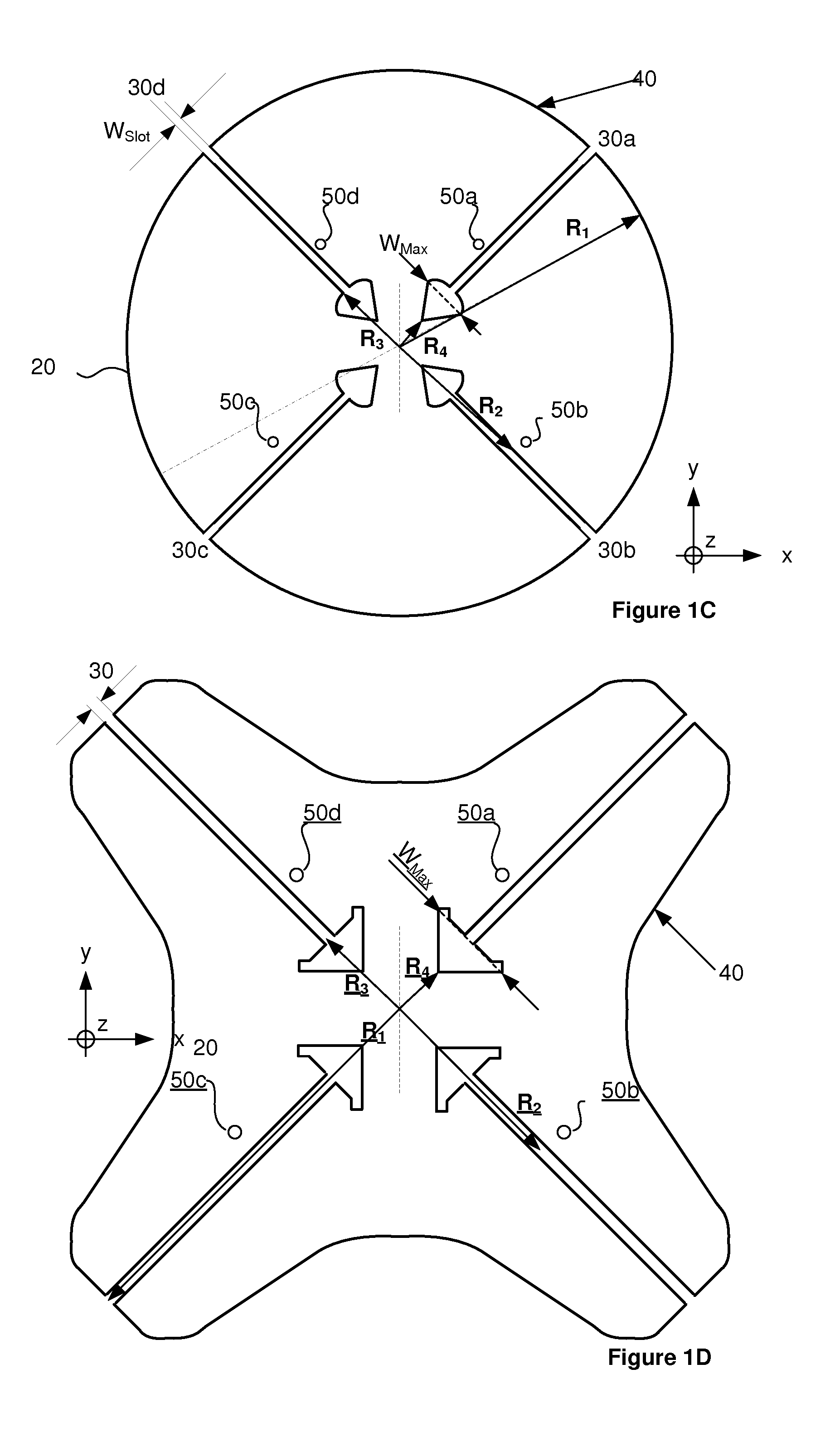
[0052]A broadband antenna 10 according to an embodiment will be described with reference to FIG. 2. The broadband antenna may interchangeably be referred to as broadband antenna element 10.

[0053]The broadband antenna comprises a conductive plate 20 comprising four slots 30a, 30b, 30c, 30d. The slots are arranged in a rotation symmetrical manner in the plate.

[0054]Each slot extends from a circumference 40, or perimetry 40, of the plate 20, which, for the purpose of this specification may be alternately referred to as a disc 20, towards a rotational symmetry center of the plate 20. Each slot 30a, 30b, 30c, 30d has an associated feed point 51a, 51b, 51c, 51d located at its associated slot.

[0055]The feed points associated with e.g. the pair 30a, 30c of oppositely arranged slots are arranged to be fed such that a main radiation propagation direction of the antenna is along the rotational symmetry axis of the plate 20.

[0056]By placing the four slots in a rotation symmetrical manner, the e...


PUM


Abstract

A broadband antenna of an antenna system comprises a conductive plate comprising four slots. The slots are arranged in a rotation symmetrical manner in the plate. Each slot extends from a circumference of the plate towards a center of the plate. Each slot has an associated feed point located at its associated slot.The feed points associated with a pair of oppositely arranged slots are arranged to be fed with radio frequency signals, such that that a main radiation propagation direction of the antenna is along the rotational symmetry axis of the plate.The antenna design enables the achievement of flexibility in terms of isolation between the two polarisations. The antenna design may further enable a reduced size and weight. The antenna design also enables an antenna unit and an antenna array.

Description

FIELD OF THE INVENTION[0001]The present invention generally relates to the field of broadband antennas.BACKGROUND OF THE INVENTION[0002]Multiband broadband antenna systems are antenna systems providing wireless signals in multiple radio frequency bands. They are commonly used in wireless communication systems, such as GSM, GPRS, EDGE, UMTS, LTE, and WiMax systems.[0003]These types of antenna systems generally include a plurality of radiating antenna elements arranged to provide a desired radiated, and received, signal beamwidth and azimuth scan angle.[0004]For broadband antennas it is desirable to achieve a near-uniform beamwidth exhibiting minimum variation over desired azimuthal degrees of coverage. Such broadband antennas generally provide equal signal coverage over a wide geographic area while simultaneously supporting multiple wireless applications. Preferrably, the beamwidth is consistent over a wide frequency bandwidth in modern wireless applications since transmission to and...

Claims


Application Information

Patent Timeline
IPC IPC(8): H01Q13/10H01Q21/24H01Q21/28H01Q21/08
CPCH01Q13/10H01Q21/28H01Q21/24H01Q21/08H01Q1/521H01Q21/29
Inventor LINDMARK, BJORN
Owner KAELUS AB
Why Eureka
Try Eureka