Unlock instant, AI-driven research and patent intelligence for your innovation.
Method for producing lithium ion secondary battery
Active Publication Date: 2016-10-20
NISSAN MOTOR CO LTD
View PDF6 Cites 2 Cited by
Summary
Abstract
Description
Claims
Application Information
AI Technical Summary
This helps you quickly interpret patents by identifying the three key elements:
Problems solved by technology
Method used
Benefits of technology
Benefits of technology
The present invention provides a method for producing a high-capacity secondary battery that can suppress degradation even when charged and discharged at high potential. This is achieved by activating the battery using a specific production method that involves multiple charge-discharge cycles followed by natural recovery and discharge at lower current density. The activation treatment improves the stability and surface structure of the positive electrode active material, leading to reduced deterioration of the battery. The technical effects of this invention include increased capacity and suppressed degradation of the battery, even at high potential.
Problems solved by technology
However, with the solid solution positive electrode active material using Li2MnO3, which is a high-capacity positive electrode material candidate disclosed in the above-described Japanese Laid-Open Patent Application No. 9-55211, there is the problem that, while the discharge capacity is large, the cycle features are poor if used under high charge-discharge potential, leading to easy deterioration upon repeated charge-discharge.
Consequently, there is the problem that, even in a lithium ion battery that uses such a solid solution positive electrode active material as a high-capacity positive electrode, cycle durability is poor under high capacity use conditions, quickly leading to deterioration when charge-discharge is carried out at high potential.
Method used
Image
Click on the blue label to locate the original text in one second.
Reading with bidirectional positioning of images and text.
Examples
example 1
[0102]In Example 1, the lithium ion secondary battery prepared above was activated by the first activation method according to the following charge-discharge steps.
[0103](Step 1) The battery was charged to 4.45V by the constant current method (equivalent to current density: 0.1 C) under a 30° C. atmosphere, paused for 10 minutes, then discharged to 2V by the constant current method (equivalent to current density: 0.02 C). This cycle was repeated twice.
[0104](Step 2) Next, the battery was charged to 4.55V by the constant current method (equivalent to current density: 0.1 C), paused for 10 minutes, then discharged to 2V by the constant current method (equivalent to current density: 0.02 C).
[0105](Step 3) Next, the battery was charged to 4.65V by the constant current method (equivalent to current density: 0.1 C), paused for 10 minutes, then discharged to 2V by the constant current method (equivalent to current density: 0.02 C).
[0106](Step 4) Finally, the battery was charged to 4.75V by...
example 2
[0107]In Example 2, the lithium ion secondary battery prepared above was activated by the second activation method according to the following charge-discharge steps.
[0108](Step 1) The battery was charged to 4.45V by the constant current method (equivalent to current density: 0.1 C) under a 30° C. atmosphere, paused for 10 minutes, then discharged to 2V by the constant current method (equivalent to current density: 0.1 C). The battery was allowed to stand idle for one hour thereafter, then discharged to 2V by the constant current method (equivalent to current density: 0.01 C). This cycle was repeated twice.
[0109](Step 2) Next, the battery was charged to 4.55V by the constant current method (equivalent to current density: 0.1 C), paused for 10 minutes, then discharged to 2V by the constant current method (equivalent to current density: 0.1 C). After one hour of pause, the battery was discharged to 2V by the constant current method (equivalent to current density: 0.01 C).
[0110](Step 3)...
example 3
[0112]In Example 3, the lithium ion secondary battery prepared above was activated by the first activation method according to the following charge-discharge steps.
[0113](Step 1) The battery was charged to 4.45V by the constant current method (equivalent to current density: 0.1 C) under a 30° C. atmosphere, paused for 10 minutes, then discharged to 3.4V by the constant current method (equivalent to current density: 0.1 C). Then, the battery was further discharged to 2V by the constant current method (equivalent to current density: 0.01 C). This cycle was repeated twice.
[0114](Step 2) Next, the battery was charged to 4.55V by the constant current method (equivalent to current density: 0.1 C), paused for 10 minutes, then discharged to 3.4V by the constant current method (equivalent to current density: 0.1 C). Then, the battery was further discharged to 2V by the constant current method (equivalent to current density: 0.01 C).
[0115](Step 3) Next, the battery was charged to 4.65V by the...
PUM
Abstract
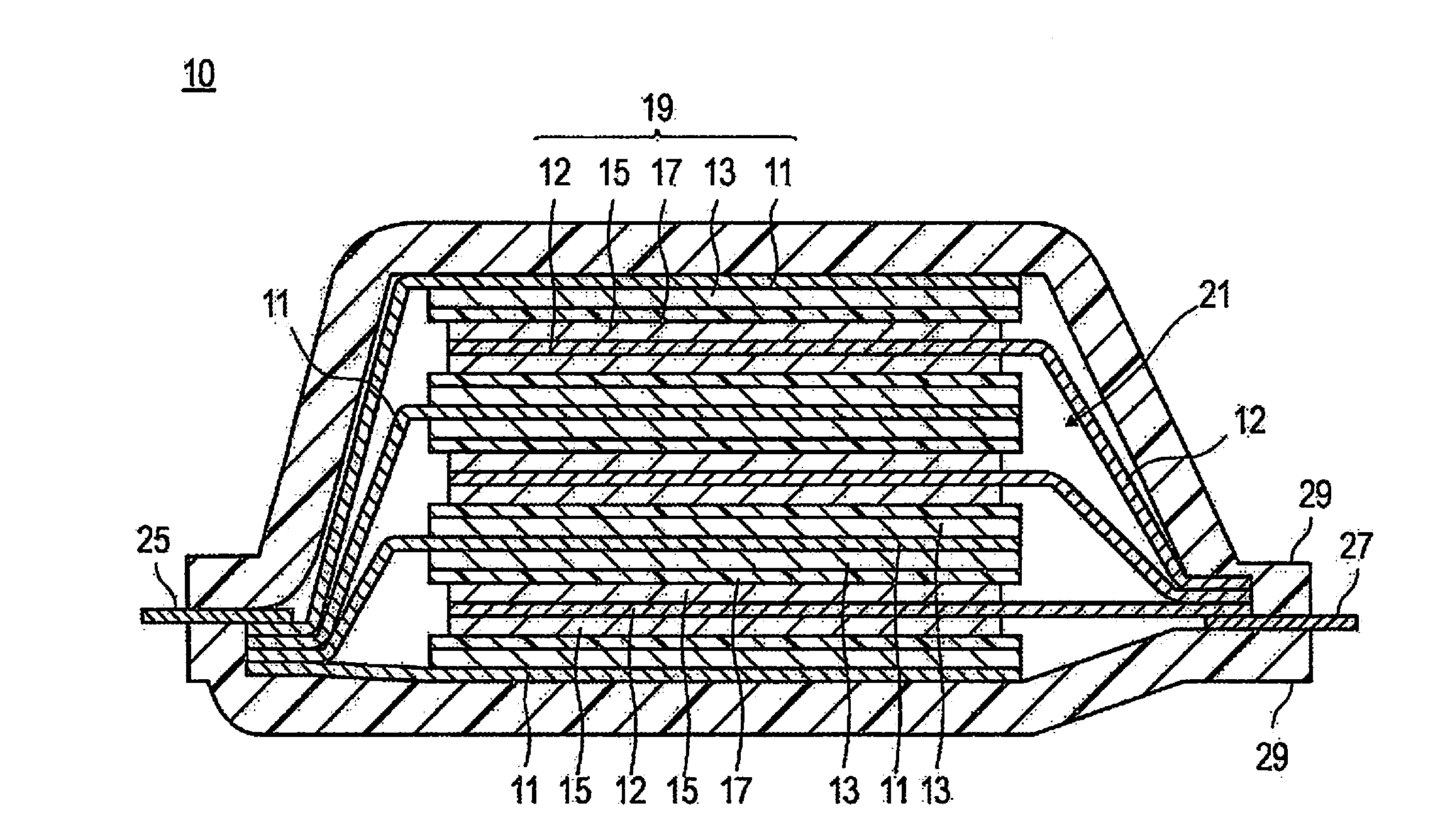
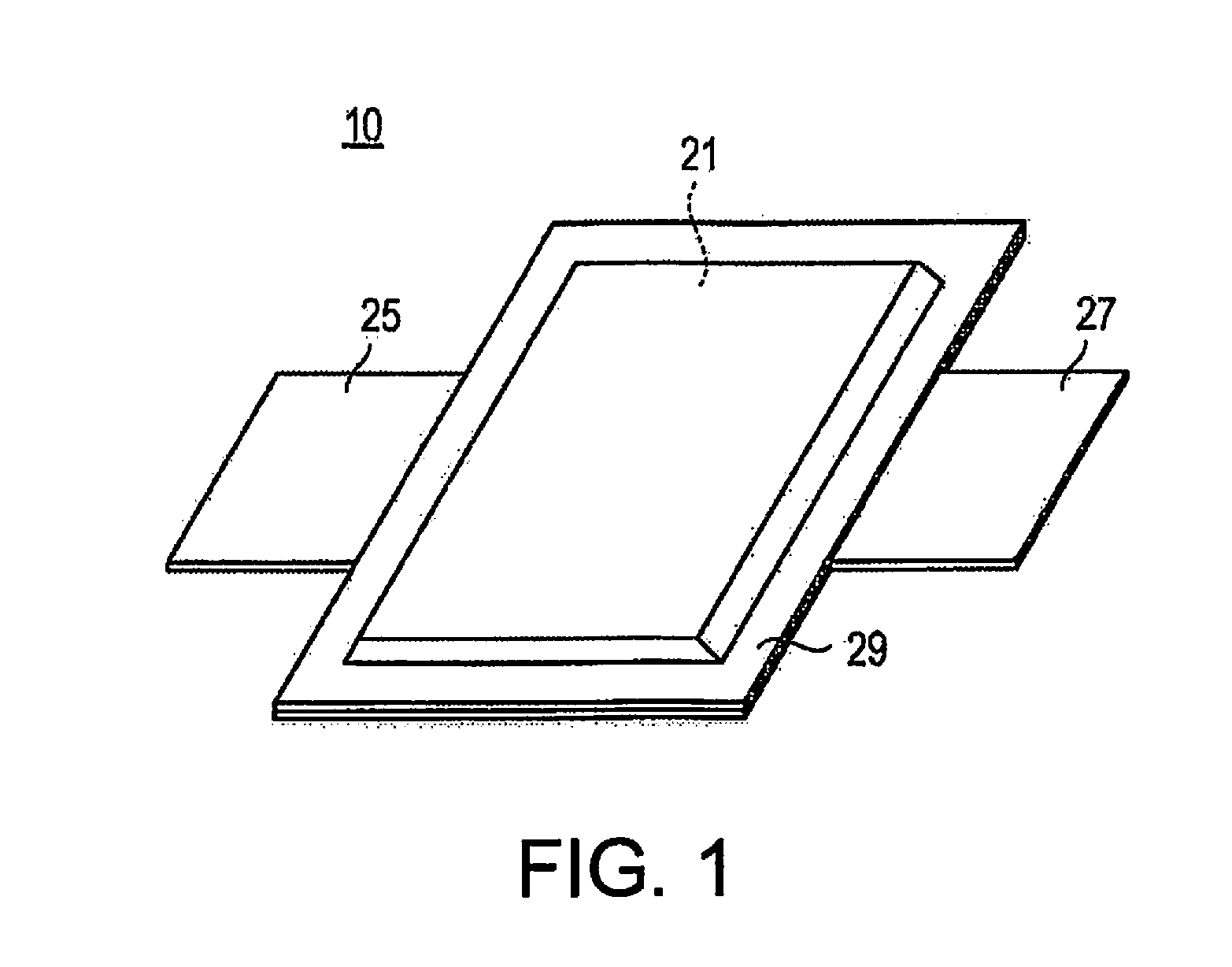
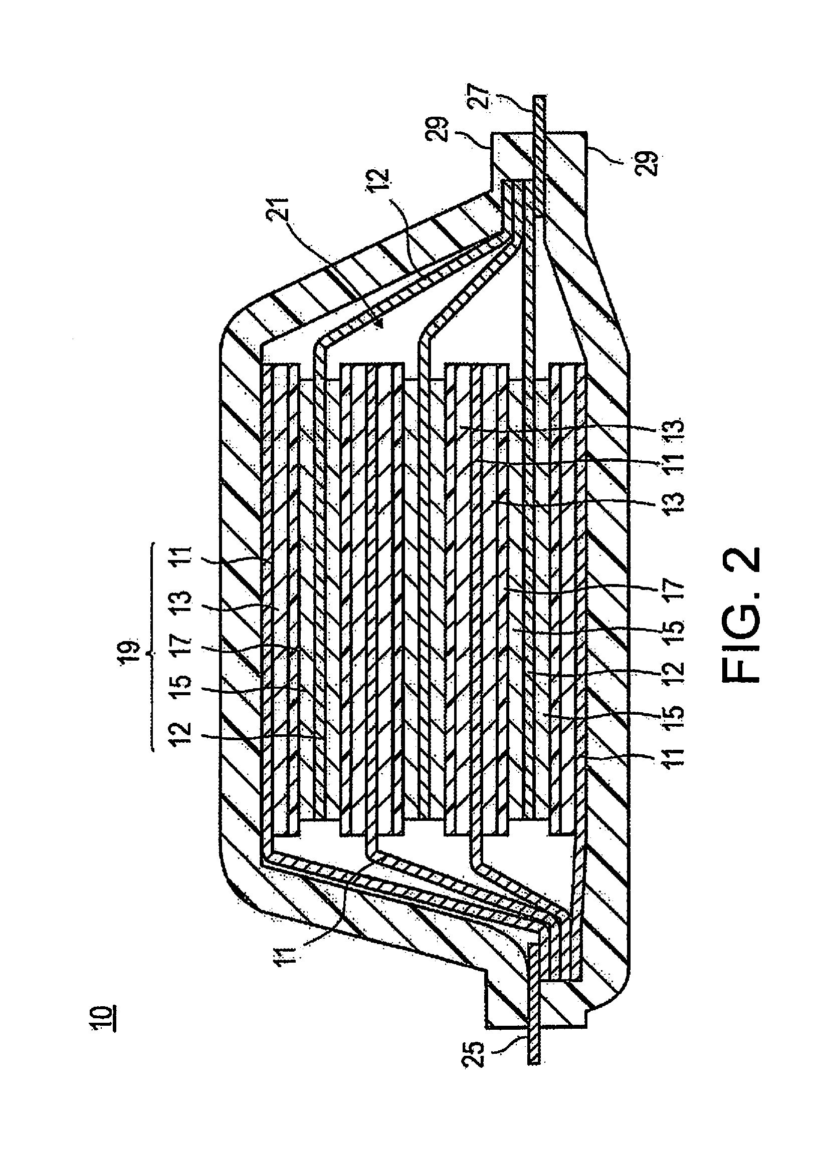
A method for producing a lithiumion secondary battery comprising the positive electrode active material of formula (1), Li(2-0.5x)Mn1-xM1.5xO3 (x satisfies 0<x<1) . . . (1) (M in the formula is a lithium-containing transition metaloxide expressed by NiaCobMncM1d (in which 0<a≦0.5, 0≦b≦0.33, 0<c≦0.5, and 0≦d≦0.1 are satisfied, the sum of a, b, c, and d becomes 1, and M1 in the formula is an element selected from Li, V, Al, Zr, Ti, Nb, Fe, Cu, Cr, Mg, and Zn)). The method comprises a step to repeat charge-discharge multiple times (charge-discharge interval), and comprises a step to discharge a at a lower current density than the current density during charge a, during the discharge of the multiple charges-discharges, or, a step to discharge b at a lower current density than the current density during charge a after the electromotive force is naturally recovered by idle b after each charge-discharge.
Description
CROSS-REFERENCE TO RELATED APPLICATIONS[0001]This application is a U.S. National stage application of International Application No. PCT / JP2014 / 082467, filed Dec. 8, 2014, which claims priority to Japanese Application No. 2014-002499, filed Jan. 9, 2014.BACKGROUND[0002]1. Field of the Invention[0003]The present invention relates to a method for producing a lithiumion secondary battery.[0004]2. Background Information[0005]In recent years, the use of various electric vehicles has been promoted with the expectation of solving environmental / energy issues. Secondary batteries are being developed intensively as a vehicle-mounted power source, such as a motor drive power source, which holds the key to the practical application of these electric vehicles. However, in order to ensure widespread use, it is necessary to increase the performance and reduce the cost of batteries. In addition, with an electric vehicle, it is necessary to bring the single-charge driving range closer to that of a g...
Claims
Application Information
Patent Timeline
Application Date:The date an application was filed.
Publication Date:The date a patent or application was officially published.
First Publication Date:The earliest publication date of a patent with the same application number.
Issue Date:Publication date of the patent grant document.
PCT Entry Date:The Entry date of PCT National Phase.
Estimated Expiry Date:The statutory expiry date of a patent right according to the Patent Law, and it is the longest term of protection that the patent right can achieve without the termination of the patent right due to other reasons(Term extension factor has been taken into account ).
Invalid Date:Actual expiry date is based on effective date or publication date of legal transaction data of invalid patent.
