Control apparatus for motor control system

a control apparatus and motor control technology, applied in control systems, multi-motor speed/torque control, electrical devices, etc., can solve the problems of increasing the number of steps involved in map data generation, and increasing the number of steps involved in designing the control apparatus. to achieve the effect of accurately reducing the total power loss of the motor control system

Active Publication Date: 2016-10-20
DENSO CORP
View PDF1 Cites 17 Cited by
  • Summary
  • Abstract
  • Description
  • Claims
  • Application Information

AI Technical Summary

Benefits of technology

[0009]It is thus desired to provide a control apparatus for a motor control system that is capable of accurately reducing total power loss of a motor control system, even in cases in which individual differences among motor control systems and changes in usage environment temperature of the motor control system are present.
[0018]Here, it is found that the total power loss of the motor control system including the respective power losses in the converter, the inverter, and the motor becomes minimum when the square wave control is being performed, based on the above-described relationship between the respective power losses in the converter, the inverter, and the motor, and the modulation factor. Therefore, when the square wave control is being performed, the total power loss can be reduced by determination of the output voltage command value of the converter at which the total power loss of the motor control system can become closer to the minimum value thereof.
[0021]As a result of the above-described decreasing correction or increasing correction, the current output voltage command value is updated such that the total power loss of the motor control system becomes closer to the minimum value thereof, during the correction-allowed period. Here, in the preset exemplary embodiment, the method for correcting the output voltage command value by the above-described decreasing correction or increasing correction is used. Therefore, the operation point of the motor control system at which the total power loss of the motor control system becomes minimum is not required to be ascertained in advance. Consequently, the total power loss of the motor control system can be accurately reduced even when individual differences among motor control systems or changes in the usage environment temperature of the motor control system are present.
[0022]In addition, in the present exemplary embodiment, even when individual differences among mass-produced motor control systems are present, the output voltage command value is corrected with focus on the power loss change amount assuming that the output voltage command value is changed by a predetermined value. Therefore, the effects that individual differences have on correction of the output voltage command value can be suppressed.

Problems solved by technology

However, in this case, there is concern that the number of steps involved in map data generation will increase, and the number of steps involved in designing of the control apparatus will increase.
However, in this case, there is concern that the number of steps involved in designing of the control apparatus will increase.
When the output voltage of the converter is low, the respective power losses in the converter and the inverter decrease compared to when the output voltage is high.
Therefore, when the modulation factor is large, the respective power losses in the converter and the inverter decrease compared to when the modulation factor is small.
As a result, when the modulation factor is greater than the prescribed value and the square wave control is being performed, the power loss in the inverter decreases compared to when the pulse width modulation control is being performed.
Therefore, when the square wave control is being performed, power loss in the motor increases compared to when the modulation factor is less than the prescribed value and the pulse width modulation control is being performed.
Therefore, in the motor control system that includes a plurality of sets of the inverter and the motor, there is concern that the number of steps involved in ascertaining in advance the operation point at which the total power loss of the system becomes minimum will become large.

Method used


Image

  • Control apparatus for motor control system
  • Control apparatus for motor control system
  • Control apparatus for motor control system

Examples


Embodiment Construction

[0043]An embodiment in which a control apparatus of the present disclosure is applied to a vehicle (such as an electric car or a hybrid car) that includes a three-phase motor as an on-board main machine will hereinafter be described with reference to the drawings.

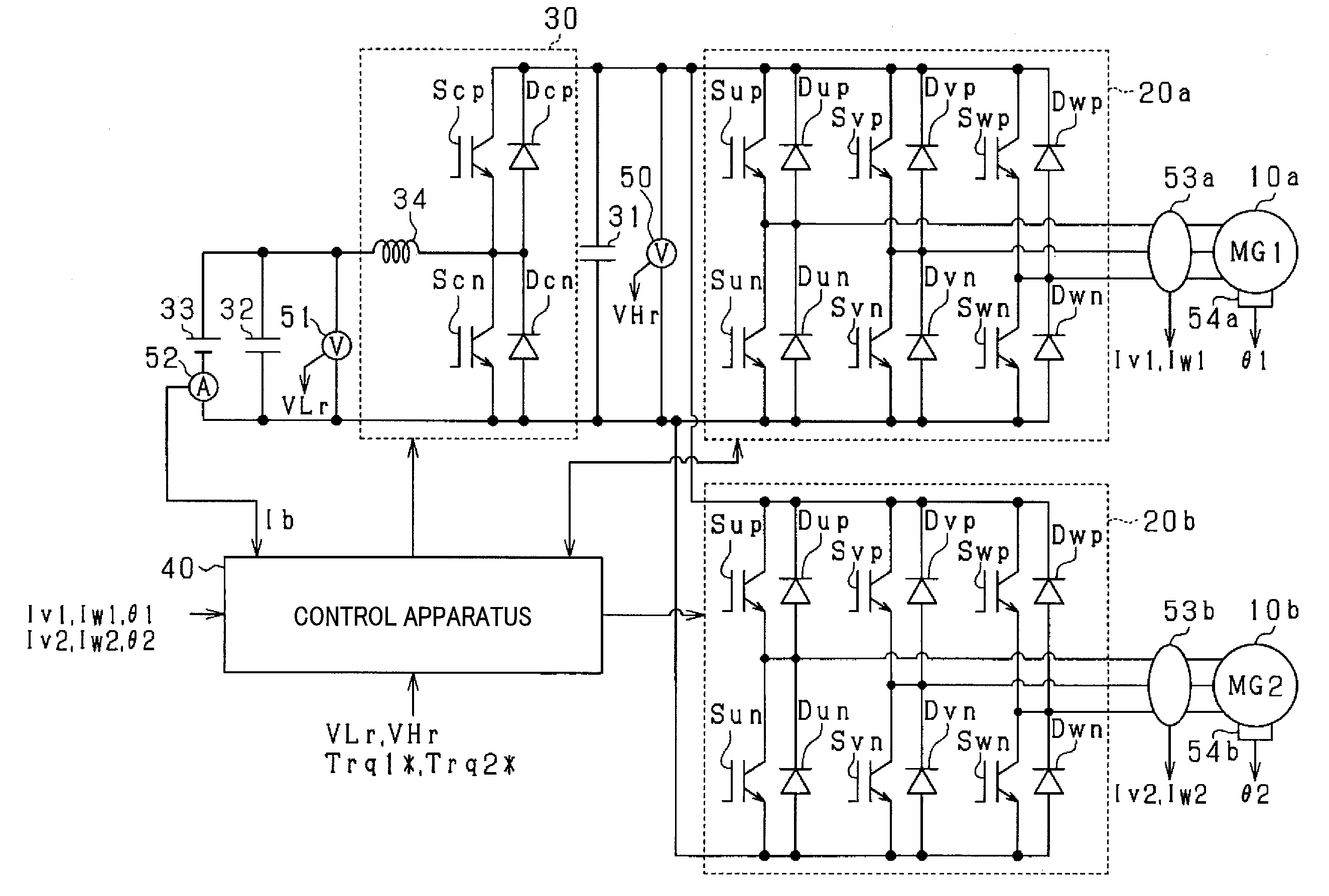
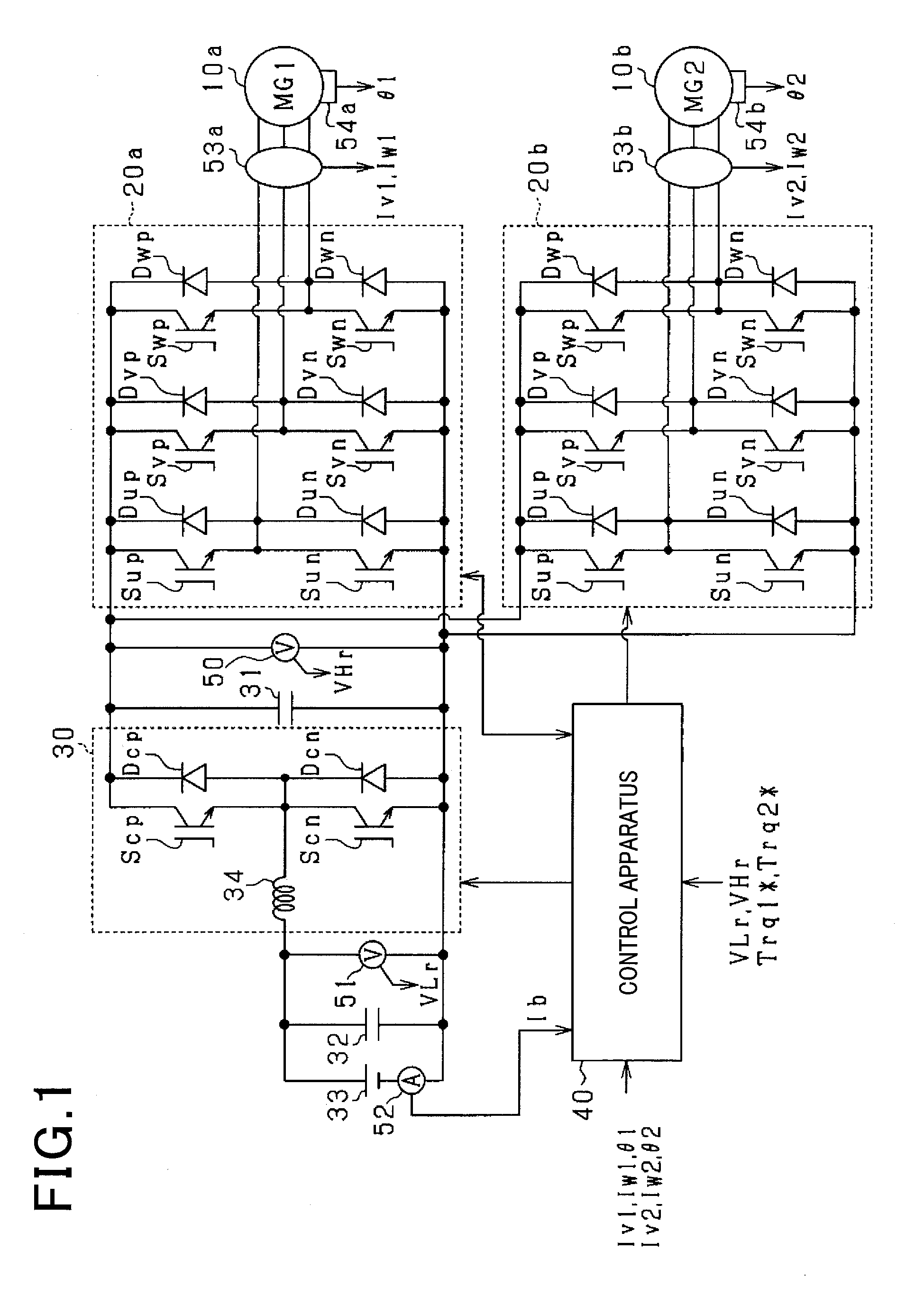
[0044]As shown in FIG. 1, a motor control system includes a first motor generator 10a, a first inverter 20a, a second motor generator 10b, a second inverter 20b, a step-up converter 30, and a control apparatus 40. According to the present embodiment, permanent magnet synchronous motors are used as the motor generators 10a and 10b. More specifically, interior permanent magnet synchronous motors (IPMSMs) that are salient pole motors are used. The first motor generator 10a serves as a power generator. The first motor generator 10a also serves as a starter that applies initial rotation to a crank shaft of a main on-board engine (not shown). The second motor generator 10b serves as an on-board main machine or the like.

[0045]The ...


PUM


Abstract

A control apparatus calculates a total loss change amount that is a power loss change amount of a motor control system including respective power loss change amounts of a converter, an inverter, and a motor of the motor control system. Based on the total loss change amount, during a correction-allowed period that is a period during which square wave control is performed, the control apparatus performs correction to decrease a current output voltage command value of the converter when the current output voltage command value is determined to be greater than the output voltage of the converter at which actual total power loss change amount becomes minimum. When the current output voltage command value is determined to be less than the output voltage of the converter at which actual total power loss change amount becomes minimum, the control apparatus performs correction to increase the current output voltage command value.

Description

CROSS-REFERENCE TO RELATED APPLICATION[0001]This application is based on and claims the benefit of priority from Japanese Patent Application No. 2015-083264, filed Apr. 15, 2015. The entire disclosure of the above application is incorporated herein by reference.BACKGROUND[0002]1. Technical Field[0003]The present disclosure relates to a control apparatus that is applicable to a motor control system. The motor control system includes a converter, an inverter, and a motor. The converter is capable of stepping up an output voltage of a direct-current power supply and outputting the stepped-up output voltage. The inverter is capable of converting the output voltage from the converter to an alternating-current voltage and outputting the alternating-current voltage. The motor is capable of being driven by the alternating-current voltage outputted from the inverter.[0004]2. Related Art[0005]As can be seen in Japanese Patent Publication No. 4635703, as this type of control apparatus, a contr...

Claims


Application Information

Patent Timeline
Patent Type & Authority Applications(United States)
IPC IPC(8): H02P6/04H02P6/08
CPCH02P6/08H02P6/04H02P21/02H02P27/085
Inventor MORII, AKIYOSHINOMURA, TETSUYA
Owner DENSO CORP
Why Eureka
Try Eureka