Cooling module with multiple parallel blowers

a technology of cooling module and blower, which is applied in the direction of electrical equipment, machine/engine, liquid fuel engine, etc., can solve the problems of increasing the challenge of electronic equipment designers to provide high-power devices in relatively small packages, inability to reduce noise, and relatively large power consumption, so as to reduce noise and improve performance, the effect of efficient and effective cooling

Inactive Publication Date: 2016-10-20
LTI HLDG INC
View PDF3 Cites 2 Cited by
  • Summary
  • Abstract
  • Description
  • Claims
  • Application Information

AI Technical Summary

Benefits of technology

[0008]By means of the present invention, electronics applications with high-density component populations may be efficiently and effectively cooled with a low-volume cooling module. The specific arrangement of forward-curved centrifugal blowers of the present invention facilitates the creation of a cooling module of low physical volume that nevertheless generates desired levels of air movement power at substantially reduced noise. Electronics chassis manufacturers, therefore, are able to achieve high performance within small-volume packages.

Problems solved by technology

Designers of electronic equipment have become increasingly challenged to provide high-power devices in relatively small packages.
Conventional system designs often employ fans that are not well matched to the system pressures, or do not move air efficiently within the space constraints, and result in unacceptable noise, and relatively large power consumption.
Relatively high aerodynamic efficiencies can be achieved with this type of air mover, but unfortunately they require high rotational speeds that typically result in unacceptable acoustic signatures.
Typical packaging constraints don't allow for proper diffusers, resulting in poor system efficiencies, and compromised acoustics.

Method used


Image

  • Cooling module with multiple parallel blowers
  • Cooling module with multiple parallel blowers
  • Cooling module with multiple parallel blowers

Examples


Embodiment Construction

[0024]The following description provides detail of various embodiments of the invention, one or more examples of which are set forth below. Each of these embodiments are provided by way of explanation of the invention, and not intended to be a limitation of the invention. Further, those skilled in the art will appreciate that various modifications and variations may be made in the present invention without departing from the scope or spirit of the invention. By way of example, those skilled in the art will recognize that features illustrated or described as part of one embodiment, may be used in another embodiment to yield a still further embodiment. Thus, it is intended that the present invention also cover such modifications and variations that come within the scope of the appended claims and their equivalents.

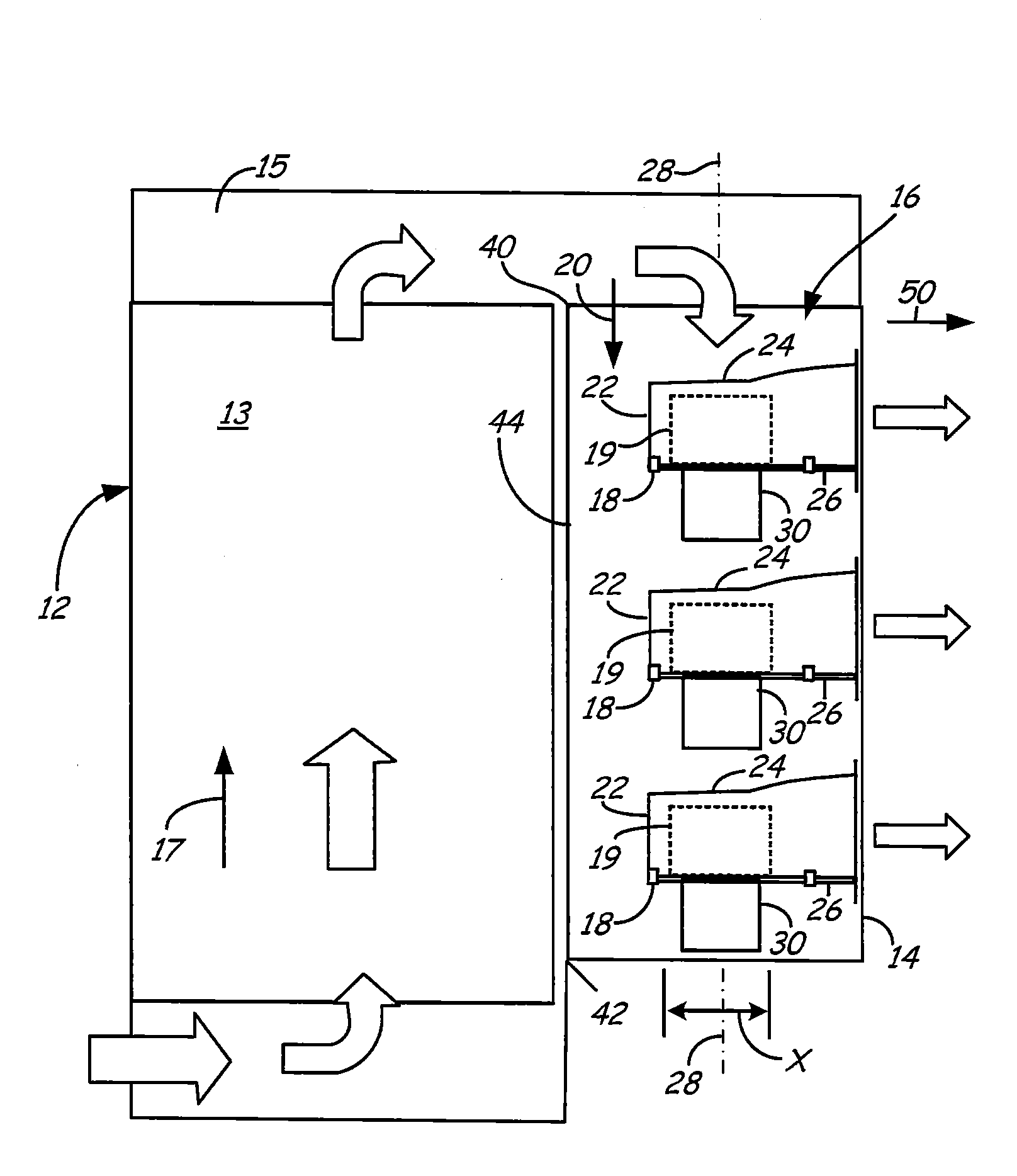
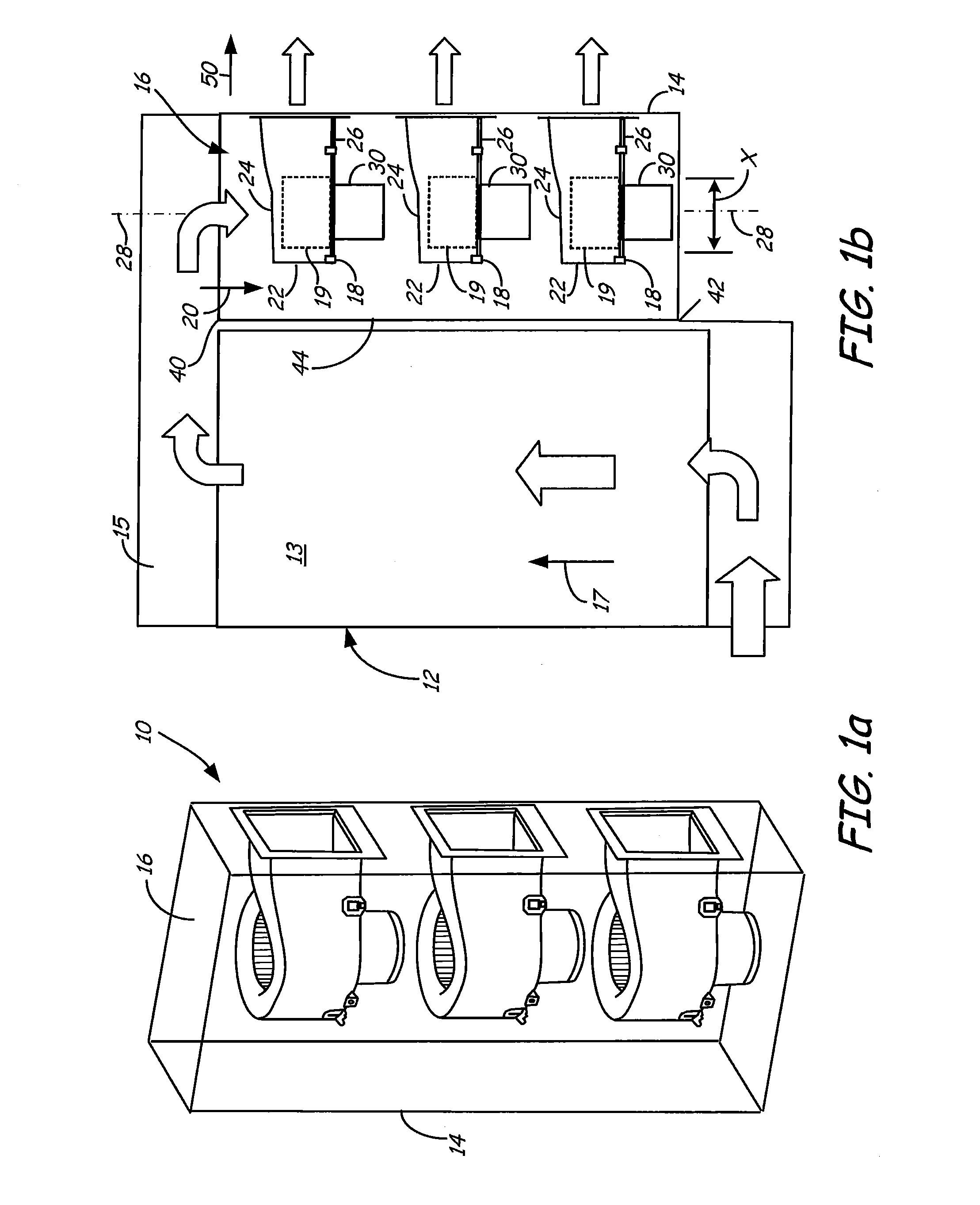
[0025]The present invention addresses the efficiency and noise issues outlined above. The preferred embodiment includes an air mover module set up to motivate air through an...


PUM


Abstract

A cooling fan module for motivating air flow through an electronics chassis includes an enclosure having an air inlet through which cooling air flow is motivated by at least two centrifugal blowers disposed within the enclosure. The centrifugal blowers operate in parallel to motivate the cooling air flow along a first direction vector, while the respective axes of rotation of the centrifugal blower impellers are in substantial axial alignment with one another, and parallel to the first direction vector.

Description

CROSS-REFERENCE TO RELATED APPLICATIONS[0001]This application claims priority to U.S. provisional Patent Application Ser. No. 61 / 356,374, filed on Jun. 18, 2010 and entitled “Cooling Module with Multiple Parallel Blowers”, and to U.S. non-provisional patent application Ser. No. 13 / 163,385, filed Jun. 17, 2011 the contents of which are being incorporated herein in their entirety.TECHNICAL FIELD OF THE INVENTION[0002]The present invention relates to cooling systems generally, and more particularly to a cooling fan module for motivating cooling air flow through an electronics chassis, wherein the cooling fan module is substantially more efficient and produces substantially less noise than conventional cooling fan arrangements, without requiring increased volume.BACKGROUND OF THE INVENTION[0003]This invention relates to a module, commonly referred to as a fan tray, designed to provide cooling flow to an electronics apparatus. Specifically, the module contains a parallel flow arrangement...

Claims


Application Information

Patent Timeline
Patent Type & Authority Applications(United States)
IPC IPC(8): H05K7/20F04D25/16F04D29/42F04D25/02F04D25/08F04D29/28F04D17/16F04D27/00
CPCH05K7/20172F04D17/16F04D25/166F04D29/4233F04D25/02F04D25/08F04D29/281F04D27/004
Inventor O'CONNOR, JOHN F.DICKINSON, ROGER B.
Owner LTI HLDG INC
Why Eureka
Try Eureka