
Method and device for setting the oscillation amplitudes of oscillating firing systems for treatment or synthesis of material

a technology of firing system and oscillating amplitude, which is applied in the direction of lighting and heating apparatus, combustion types, combustion processes, etc., can solve the problems of significant increase in mechanical and/or thermal load of the plant structure, increased noise emission from the combustion process to the plant environment, and significant problem for occupational safety and reasonable working conditions

Inactive Publication Date: 2016-10-27
BUCHNER HORST
View PDF1 Cites 1 Cited by
  • Summary
  • Abstract
  • Description
  • Claims
  • Application Information

AI Technical Summary

Benefits of technology

The patent text describes a method to modify the amplitude of oscillation in a furnace without needing to change other parameters. This allows for adjusting the flow and pressure in the combustion chamber, which can improve the performance of the furnace. The method can also adjust the frequency of the oscillation without changing the plant-specific setting.

Problems solved by technology

As against steady-state operation of the furnace, the occurrence of these combustion instabilities often brings about a modified pollutant emission behaviour and causes, in addition to increased noise pollution of the plant environment, a significantly increased mechanical and / or thermal load of the plant structure (e.g., combustion liners, combustion chamber liner, etc.), which can lead to destruction of the furnace or of individual components.
However, quite different is the situation in a small number of very special combustion-technical systems, in which the above illustrated phenomenon of self-excited, periodic combustion instability is caused deliberately.
Further, increased noise emission from the combustion process to the plant environment poses a significant problem for occupational safety and reasonable working conditions.
In fact, these measures are not appropriate as the change in these parameters and other important process parameters are changed, which significantly influence the material properties of the products treated.
As the fuel and / or air feeding pipe is now to be connected upstream of the burner outlet with an oscillation volume, there is the possibility that pulsating pressure acting at the burner outlet in the combustion chamber can impact the amount of inflowing gas.

Method used


Image

  • Method and device for setting the oscillation amplitudes of oscillating firing systems for treatment or synthesis of material
  • Method and device for setting the oscillation amplitudes of oscillating firing systems for treatment or synthesis of material
  • Method and device for setting the oscillation amplitudes of oscillating firing systems for treatment or synthesis of material

Examples


Embodiment Construction

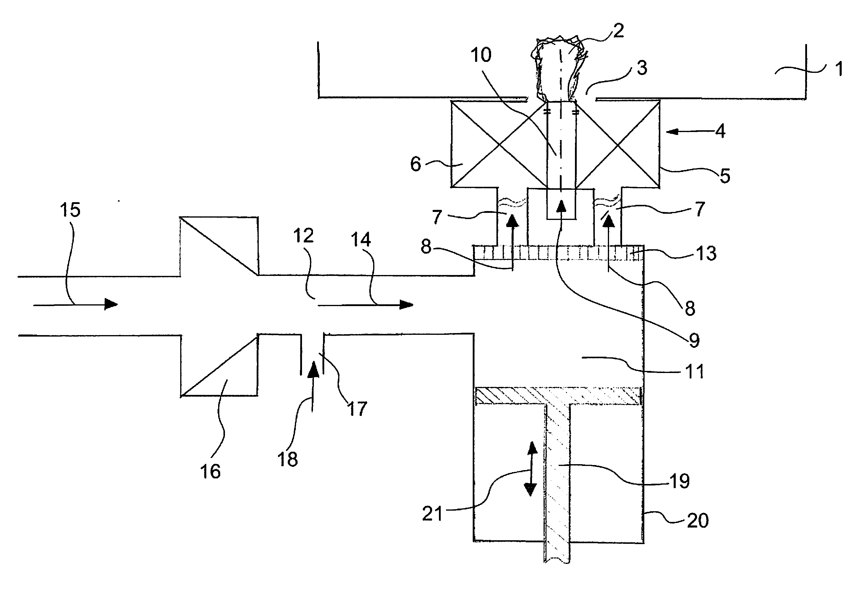
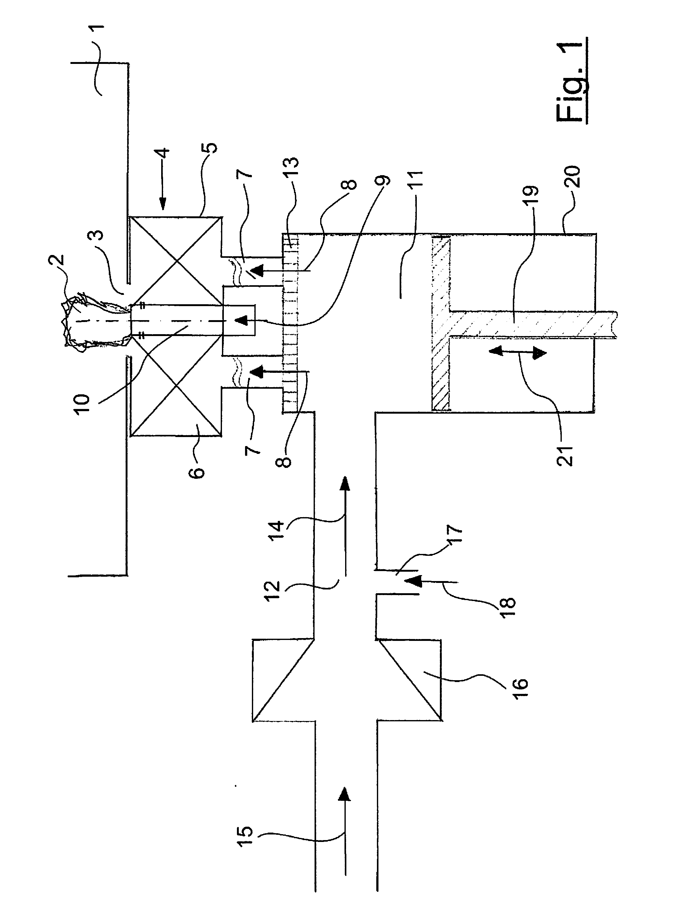
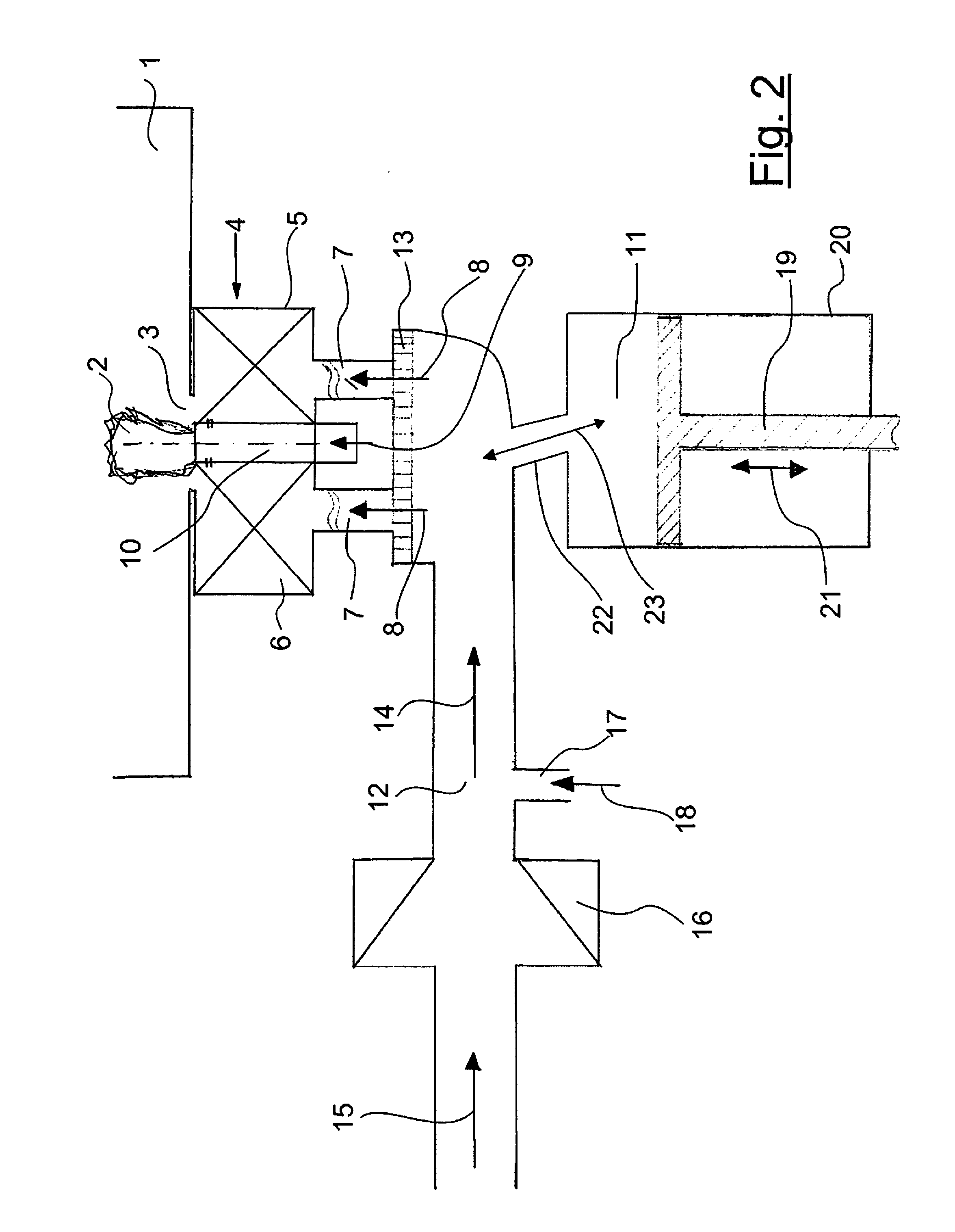
[0063]FIG. 1 shows a schematic diagram of a device according to an embodiment.

[0064]A combustion chamber 1 can be seen here, into which a flame 2 is directed.

[0065]The flame 2 forms at a burner outlet 3 of a burner 4. The flow-technical or fluidical sections of the device lying upstream of the burner outlet of the device are considered a cold side of the burner.

[0066]The flame 2 pulsates and causes a pulsation of an existing plant-specific resonating gas column being in the combustion chamber and / or in a reactor chamber downstream of this reactor chamber. Into this combustion chamber or the reactor chamber, a reactant is fed, that then is treated in the oscillating gas column of hot gas, and finally the product thus produced is removed from the hot gas stream, for example, by a hot gas filter, a cyclone or the like.

[0067]The pulsation of the flame 2 is a self-excited combustion instability, wherein the frequency of their self-excited oscillation is determined in large part by the ge...


PUM


Abstract

An oscillating firing system for targeted adjustment / readjustment of amplitudes of oscillations of static pressure and / or hot gas velocity in an oscillating firing system for thermal treatment of materials or materials synthesis includes at least one burner, with which an oscillating (pulsating) flame is generated, and at least one combustion chamber (resonator), into which the flame is directed. Upstream of the burner outlet an oscillation volume is inserted into the supply lines leading to the burner through which oscillation volume air, fuel or fuel-air mixture can flow. Preferably, the size of the oscillation volume may be adjustable. Thus, it is possible to change the amplitude of oscillation.

Description

CROSS-REFERENCE TO RELATED APPLICATIONS[0001]The present application claims priority under 35 USC 119 to German Patent Application Serial No. 10 2015 005 224.1 filed Apr. 23, 2015, the entire disclosure of which is incorporated herein by reference.FIELD OF THE INVENTION[0002]The present invention relates to a method and apparatus for setting the oscillation amplitudes of oscillating firing systems for treatment or synthesis of materials. More specifically, the invention relates to a process for selective adjustment of oscillation amplitude (oscillation level) of an oscillating combustion process in an oscillating firing system (e.g., a pulse dryer, pulse combustor, pulsation reactor) in a plant for the thermal treatment or synthesis of materials, having at least one burner, which provides a burner outlet to which a fuel and / or air is fed via a pipe and in which a pulsating flame is present forming at the burner outlet, which burns in a combustion chamber, and having at least one gas...

Claims


Application Information

Patent Timeline
IPC IPC(8): F23C15/00F23N5/00
CPCF23N5/00F23C15/00F23D14/70F23N5/16F23R2900/00014F23N2241/20B01J19/285
Inventor BUCHNER, HORST
Owner BUCHNER HORST
Learn More