Driving device

a driving device and driving technology, applied in the direction of machines/engines, vehicle cleaning, instruments, etc., can solve the problems of increasing power consumption, reducing the size of the driving device, and unable to achieve the reduction of manufacturing costs, so as to achieve the effect of stably displacing an object and simple structur

Inactive Publication Date: 2016-10-27
MURATA MFG CO LTD
View PDF0 Cites 23 Cited by
  • Summary
  • Abstract
  • Description
  • Claims
  • Application Information

AI Technical Summary

Benefits of technology

[0006]Accordingly, it is a main object of the present disclosure to provide a driving device that is capable of stably displacing an object by using a simple structure.
[0017]As a result, a high torque can be obtained even if the line width of the shape-memory alloy member is small. In addition, by setting the line width of the shape-memory alloy member to be small, the response characteristic of the shape-memory alloy member with respect to energization and the displacement characteristic of the object are improved. As a result, the object can be stably displaced by using a simple structure.

Problems solved by technology

As a result, in the related art, there has been a problem of increased power consumption when energizing the shape-memory alloy member.
In addition, in the related art, there has been a problem in that, since the structure of the converter that is used for determining the rotation angle of the blade is complex, a reduction in the size of the driving device and a reduction in the manufacturing costs cannot be achieved.

Method used


Image

  • Driving device
  • Driving device
  • Driving device

Examples


Embodiment Construction

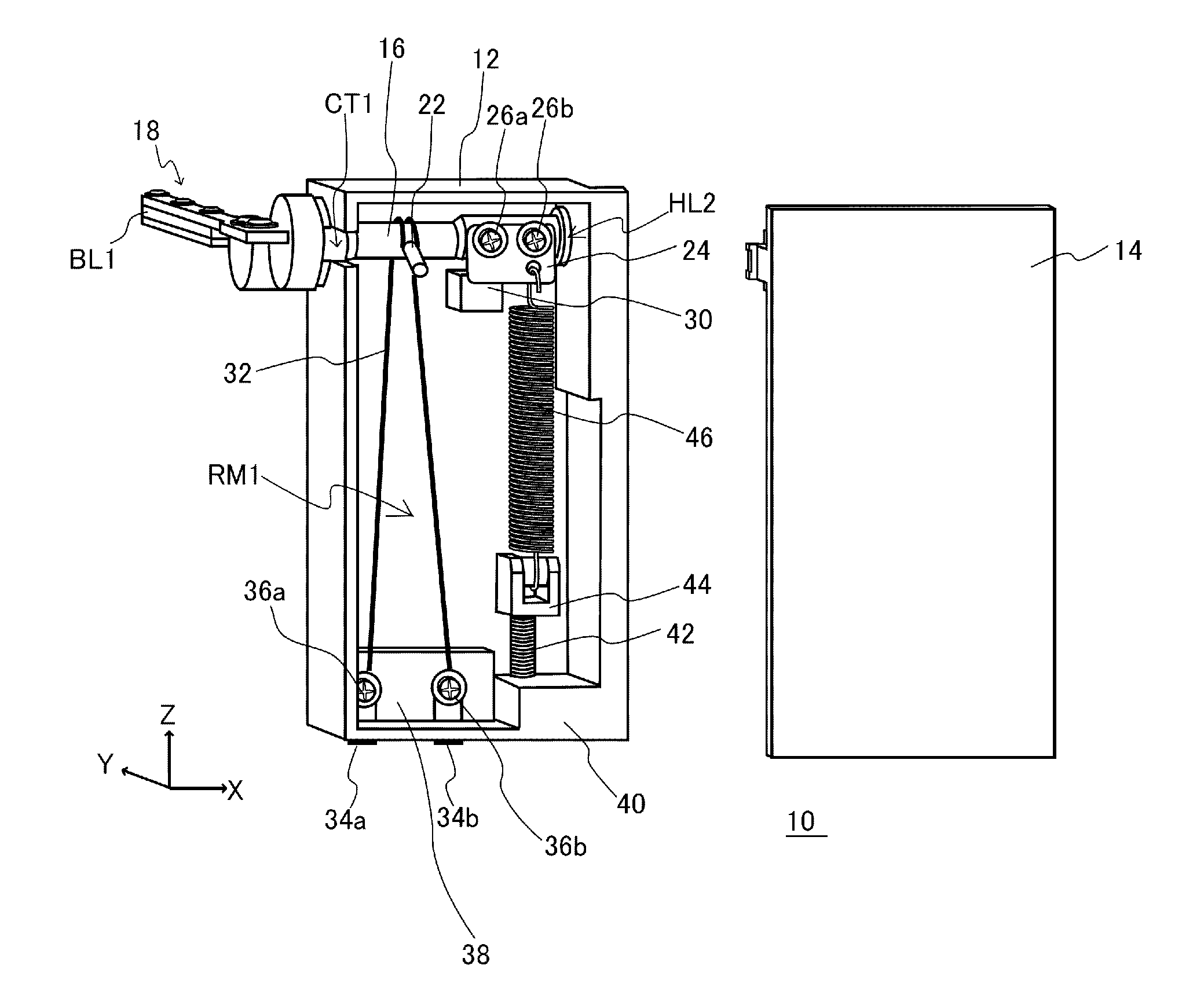
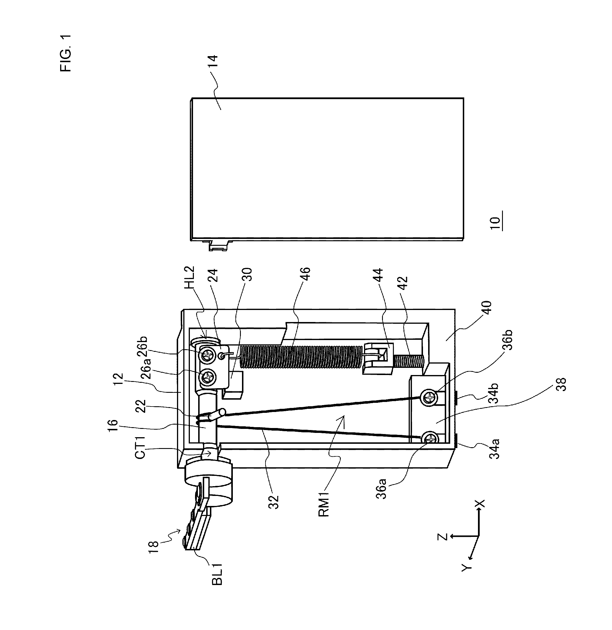
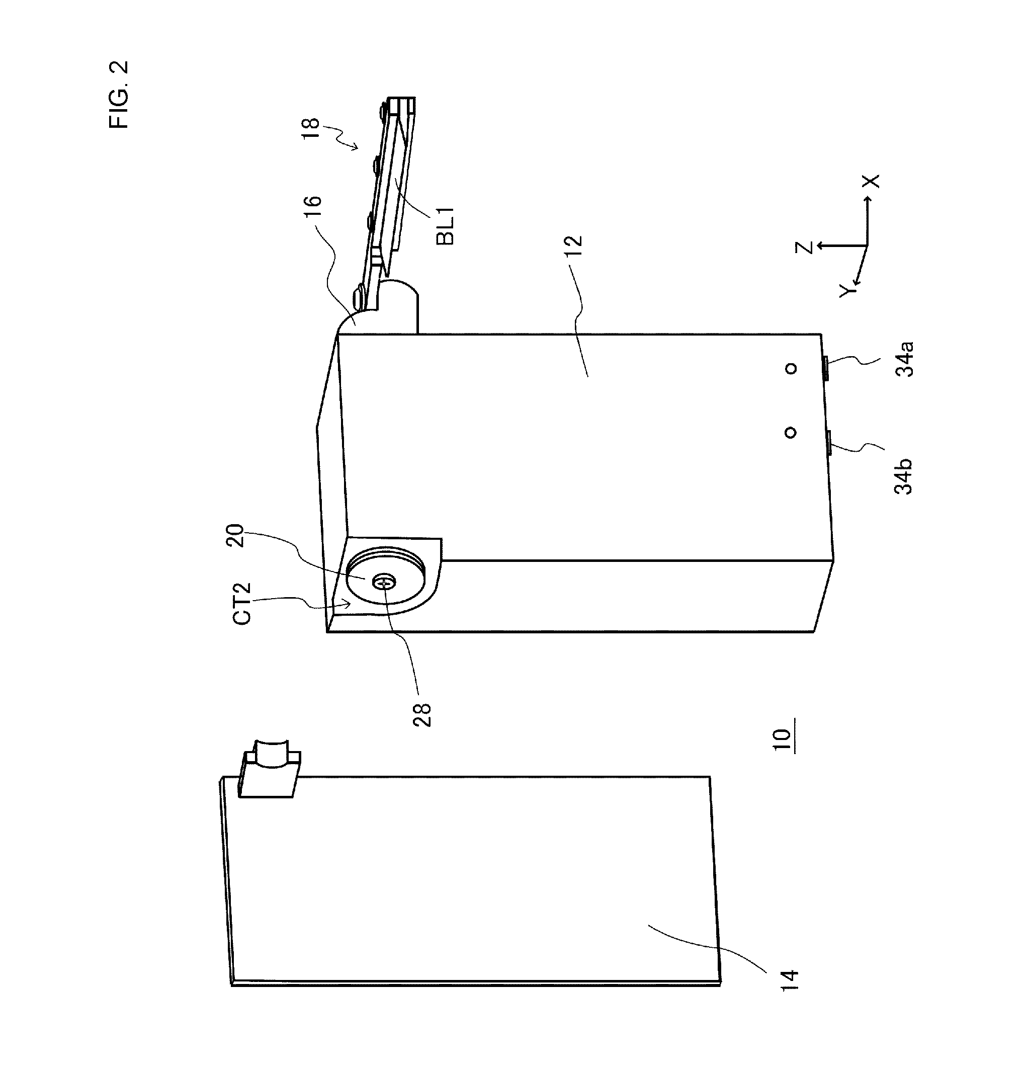
[0038]Referring to FIG. 1 to FIG. 3, a raindrop removal device 10 according to an embodiment of the present invention is a device that is used for removing raindrops deposited on, for example, a lens of a rear camera that is mounted on a rear portion of an automobile, and the raindrop removal device 10 includes a housing 12 that has a rectangular parallelepiped shape and that includes an accommodating chamber RM1. An X-axis is used to indicate the width direction of the housing 12, a Y-axis is used to indicate the thickness direction of the housing 12, and a Z-axis is used to indicate the height direction of the housing 12. In this case, the accommodating chamber RM1 is open in a negative Y-axis direction. A lid 14 is formed in a plate-like shape and has a main surface having the same size as that of a main surface of the housing 12. When the lid 14 is placed on the housing 12 from the negative Y-axis direction in a position in which side surfaces of the lid 14 are flush with corres...


PUM


Abstract

A rotary shaft supported by a housing so as to be capable of rotating in a forward rotation direction and a reverse rotation direction. A shape-memory alloy member having a wire-like shape urges, by thermally contracting, the rotary shaft by applying an external force in the forward rotation direction. A bias spring urges the rotary shaft by applying an external force in the reverse rotation direction. A wiper is displaced along with rotation of the rotary shaft. The shape-memory alloy member is arranged such that, when a thermal contraction force is divided into a first partial thermal contraction force in the forward rotation direction and a second partial thermal contraction force in a length direction of the rotary shaft, the first partial thermal contraction force is larger than the second partial thermal contraction force.

Description

CROSS-REFERENCE TO RELATED APPLICATIONS[0001]The present application is a continuation of PCT / JP2015 / 050134 filed Jan. 6, 2015, which claims priority to Japanese Patent Application No. 2014-013214, filed Jan. 28, 2014, the entire contents of each of which are incorporated herein by reference.FIELD OF THE INVENTION[0002]The present disclosure relates to driving devices, and more particularly to a driving device that is applied to a foreign-matter removal device, which removes foreign matters such as raindrops and dust, and that displaces an object by rotational operation of a rotary shaft.BACKGROUND[0003]An example of this type of driving device is disclosed in Patent Document 1. According to this related art, a shape-memory alloy member that is included in a driving unit generates heat by itself by being energized and contracts at a temperature above its transformation temperature. In addition, the shape-memory alloy member is formed in a coil shape so as to increase an operating ra...

Claims


Application Information

Patent Timeline
Patent Type & Authority Applications(United States)
IPC IPC(8): H02N10/00B60S1/56F03G7/06
CPCH02N10/00B60S1/566F03G7/065G02B27/0006
Inventor KOTANI, KENICHI
Owner MURATA MFG CO LTD
Why Eureka
Try Eureka