Method and circuit to reduce power consumption of optical transmitter

Inactive Publication Date: 2016-10-27
ALCATEL-LUCENT USA INC
View PDF4 Cites 2 Cited by
  • Summary
  • Abstract
  • Description
  • Claims
  • Application Information

AI Technical Summary

Benefits of technology

[0008]Still yet another aspect of this disclosure provides a method of operating an optical transmitter. The method includes generating a modified modulation c

Problems solved by technology

In an access network, an optical transceiv

Method used


Image

  • Method and circuit to reduce power consumption of optical transmitter
  • Method and circuit to reduce power consumption of optical transmitter
  • Method and circuit to reduce power consumption of optical transmitter

Examples


Embodiment Construction

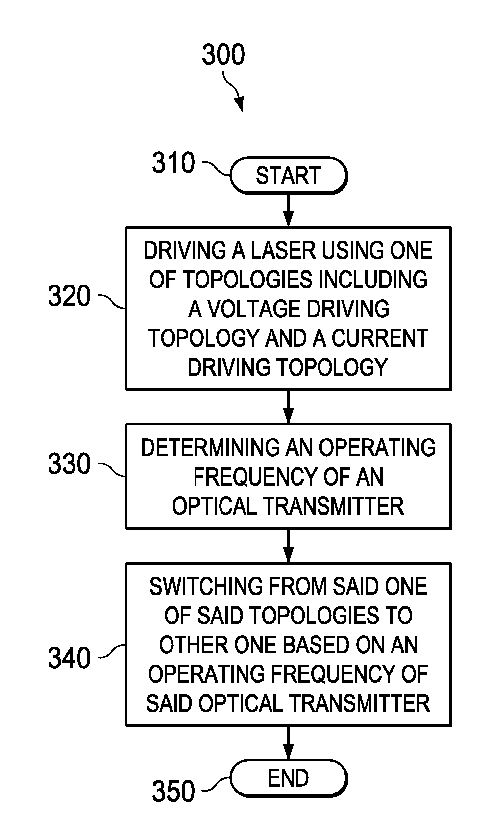
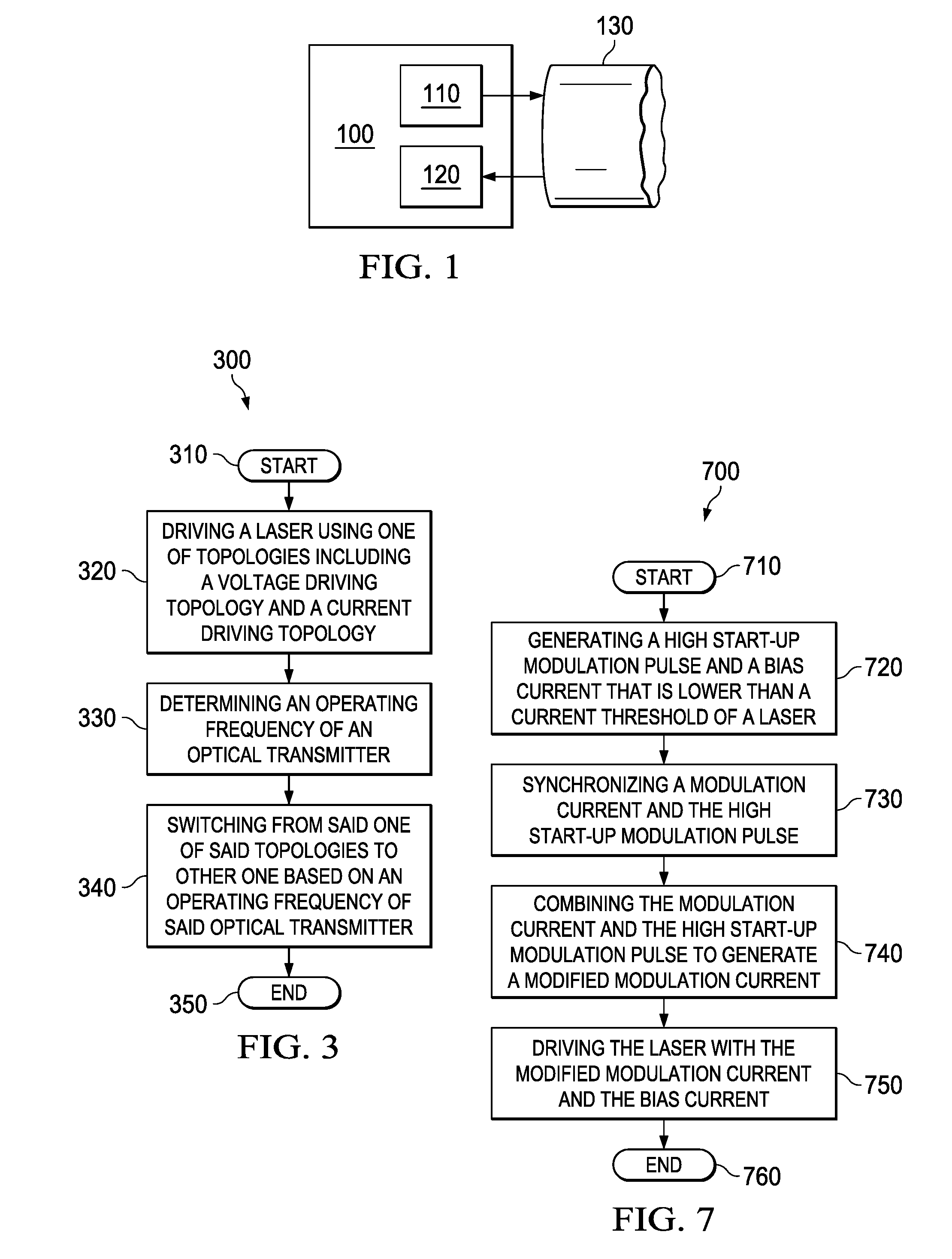
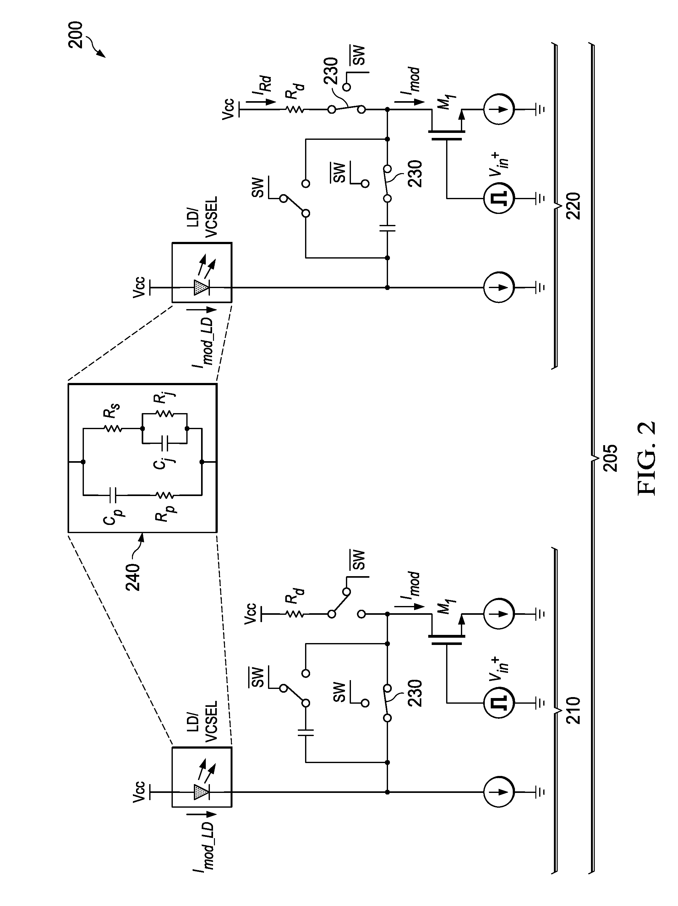
[0017]One of the ways to reduce the power consumption of an optical transmitter is reducing the transmitter's modulation current. While optimizing the modulation current based on the link condition may be effective in some instances, it has been recognized that changing the transmitter's laser driving topology from the conventional voltage-driving topology (VDT) to a current-driving topology (CDT) can be more effective.

[0018]The CDT uses less modulation current than the VDP because it lacks the VDT's parallel load matching resistor. But due to the absence of such a resistor, the CDT has higher output impedance and a smaller charging and discharging time constant and hence, a lower bandwidth than the VDT. As such, while the CDT consumes less power than the VDP, it is not a preferred topology for a high frequency / bandwidth operation, in which today's optical transmitters are often used.

[0019]Another way to reduce the power consumption of an optical transmitter is using a low bias curr...


PUM


Abstract

Various embodiments of an optical transmitter and a method of operating an optical transmitter are disclosed. In one embodiment, the optical transmitter includes a laser and a laser driver configured to drive the laser using either a voltage driving topology (CDT) or a current-driving topology (VDT). The laser driver includes a switch that is configured to switch between the CDT and the CDT based on an operating frequency of the optical transmitter.

Description

CROSS-REFERENCE TO RELATED APPLICATION[0001]This application claims the benefit of U.S. Provisional Application Ser. No. 62 / 152,582, filed by Chow, et al., on Apr. 24, 2015, entitled “Method and Circuit to Reduce Power Consumption of Optical Transmitter,” commonly assigned with this application and incorporated herein by reference.TECHNICAL FIELD[0002]This disclosure is directed to an optical communication system and, more specifically, to an optical transmitter and a method of operating thereof.BACKGROUND[0003]This section introduces aspects that may be helpful in facilitating a better understanding of the disclosure. Accordingly, the statements of this section are to be read in this light and are not to be understood as admissions about what is in the prior art or what is not in the prior art.[0004]An optical transceiver is an integrated circuit that uses fiber optic technology to communicate among devices such as Digital Video Disc players and optical local area networks. An opti...

Claims


Application Information

Patent Timeline
IPC IPC(8): H04B10/564H04B10/524H04L7/00H04B10/50
CPCH04B10/564H04L7/0075H04B10/524H04B10/504H01S5/0427H01S5/06213
Inventor CHOW, HUNGKEILI, JIELEE, KA LUN
Owner ALCATEL-LUCENT USA INC
Why Eureka
Try Eureka