System and method for maintaining efficiency of a fractal heat sink

a heat sink and fractal technology, applied in the field of heat sinks, can solve the problems of high temperature, dust or its binder pyrolysis, strain in the dust layer, etc., and achieve the effects of reducing the narrow band acoustic resonance, reducing flow rate, and reducing the flow ra

Active Publication Date: 2016-11-03
FRACTAL HEATSINK TECH
View PDF8 Cites 31 Cited by
  • Summary
  • Abstract
  • Description
  • Claims
  • Application Information

AI Technical Summary

Benefits of technology

[0062]In a preferred embodiment, a heatsink employed according to the present technology provides a branched 3D network of elements, which have a high surface area and, especially, near the terminal branches, have microstructured surfaces. As a result, dust may accumulate on the surfaces, resulting in decreased surface area as the dust obscures the microstructuring, increased thermal resistance, and deoptimized air flow patterns. Therefore, various technologies may be provided to reduce or eliminate the dust deposition on the surfaces than may occur in real-world environments:

Problems solved by technology

In various cases, the physical effect sought to be employed to prevent dust accumulation or to dislodge the dust may impair or risk impairing the device being protected by the heatsink.
For example, pyrolysis of the dust or its binder requires high temperatures, which would normally diffuse back to the device being protected.
Therefore, if the heating was performed as periodic pulses, the tips of the branched network would heat, and that heating would tend to reduce binding of the dust and cause a thermal expansion that would cause a strain in the dust layer that would reduce adhesion.
Therefore, the dust layer would be disrupted.
The use of vibration, wither continuous or pulsed, may cause damage to the device protected by the heatsink.

Method used


Image

  • System and method for maintaining efficiency of a fractal heat sink
  • System and method for maintaining efficiency of a fractal heat sink
  • System and method for maintaining efficiency of a fractal heat sink

Examples


Embodiment Construction

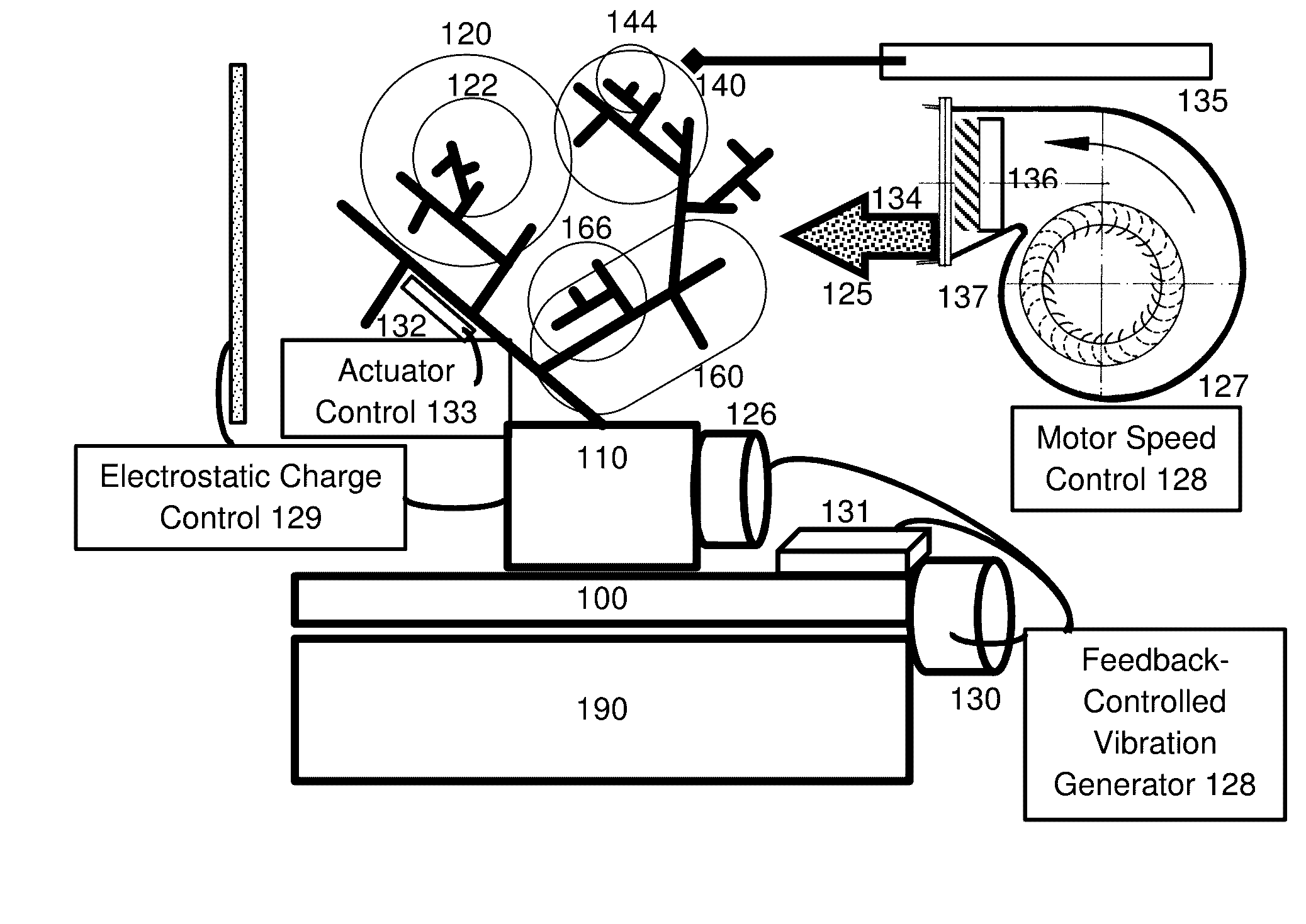
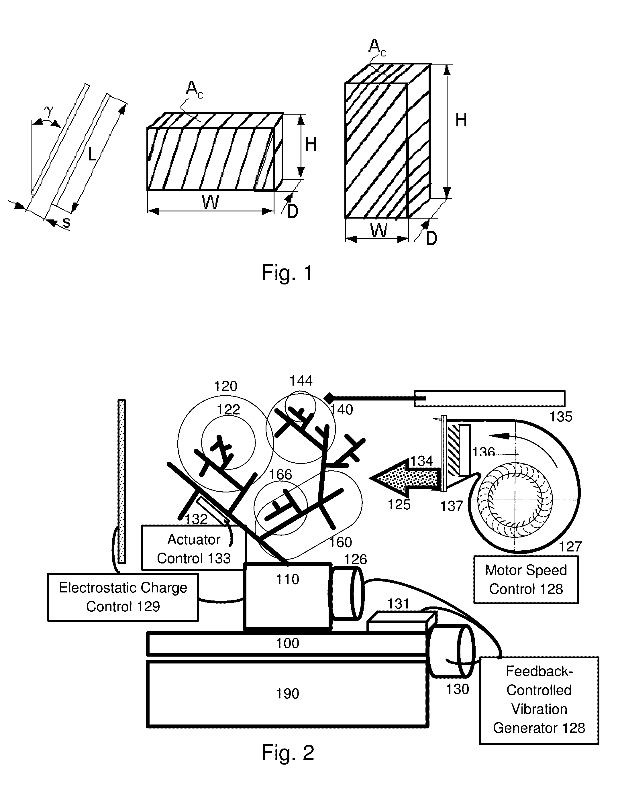
[0181]FIG. 2 illustrates a heatsink implementing a first embodiment of this invention. Note that the illustration is in two dimensions, but a three dimensional embodiment is both possible and preferred. There is a heat transfer surface 100 that allows the heatsink to rest comfortably on a surface, such as the solid to be cooled 190. In the illustrated embodiment, the heat transfer surface 100 is roughly planar, having a closed Euclidian cross-section on the bottom. However, it might also have another shape, for example if the solid to be cooled does not have a planar face. The heat transfer surface may also comprise an anisotropic vibration transfer thermal interface material, such as a braided or straight fine copper wire bundle. Such a bundle advantageously has strands of different length, which, for example, could permit destructive interference of vibrations transmitted along each strand. A fractal-shaped heat exchange device begins at point 110. The base of the fractal-shaped h...


PUM


Abstract

A heatsink comprising a heat exchange device having a plurality of heat exchange elements each having a surface boundary with respect to a heat transfer fluid, having successive elements or regions having varying size scales. According to one embodiment, an accumulation of dust or particles on a surface of the heatsink is reduced by a removal mechanism. The mechanism can be thermal pyrolysis, vibration, blowing, etc. In the case of vibration, adverse effects on the system to be cooled may be minimized by an active or passive vibration suppression system.

Description

CROSS REFERENCE TO RELATED APPLICATIONS[0001]The present application is a Continuation in part of U.S. patent application Ser. No. 14 / 984,756, filed Dec. 30, 2015, now pending; and U.S. patent application Ser. No. 14 / 817,962, filed Aug. 4, 2015, now pending; both of which claim priority from U.S. patent application Ser. No. 13 / 106,640, filed May 12, 2011, now U.S. Pat. No. 9,228,785, issued Jan. 5, 2016, which is a non-provisional of, and claims benefit of priority from, U.S. Provisional Patent Application No. 61 / 331,103, filed May 4, 2010. PCT / IB11 / 01026, filed May 13, 2011, claims benefit of priority from U.S. Provisional Patent Application No. 61 / 331,103, filed May 4, 2010. The entirety of these related applications are expressly incorporated herein by reference.FIELD OF THE INVENTION[0002]This invention relates to the field of heatsinks or devices that transfer heat between a concentrated source or sink and a fluid, and systems and methods for maintaining the efficiency of the h...

Claims


Application Information

Patent Timeline
Patent Type & Authority Applications(United States)
IPC IPC(8): F28F13/06F28D15/00
CPCF28F13/06F28D15/00F28F3/02F28F13/12F28G1/16F28G7/00F28G9/00F28G13/00F28G15/003F28F2215/10F28F2255/14
Inventor POLTORAK, ALEXANDER
Owner FRACTAL HEATSINK TECH
Why Eureka
Try Eureka