
Touch Sensor Integrated Type Display Device

Active Publication Date: 2016-11-03
LG DISPLAY CO LTD
View PDF7 Cites 37 Cited by
  • Summary
  • Abstract
  • Description
  • Claims
  • Application Information

AI Technical Summary

Benefits of technology

The patent text discusses the use of in-cell type touch sensors and self capacitive touch sensors. The in-cell type touch sensor is a type of touch sensor that can be embedded within a display device, making it thinner and more durable. This type of touch sensor has a lower touch accuracy but is more commonly used due to its cost-effectiveness and simplicity. The self capacitive touch sensor, on the other hand, has better touch accuracy but is more expensive and complicated to use. The patent text also mentions the use of a coupling construction that increases the mutual capacitance between adjacent touch / common electrodes, resulting in improved touch resolution.

Problems solved by technology

However, when the user makes use of these input devices, the user's dissatisfaction with the input devices increase because the user is required to learn how to use the input devices and the input devices occupy space.
Therefore, it is difficult to accurately recognize a touch position because of the parasitic capacitance.
Further, because a plurality of touch driving lines for a touch driving mode and a plurality of touch sensing lines for a touch sensing have to be formed on the common electrode for the multi-touch recognition of the mutual capacitive touch sensor, the mutual capacitive touch sensor requires a very complex line structure.
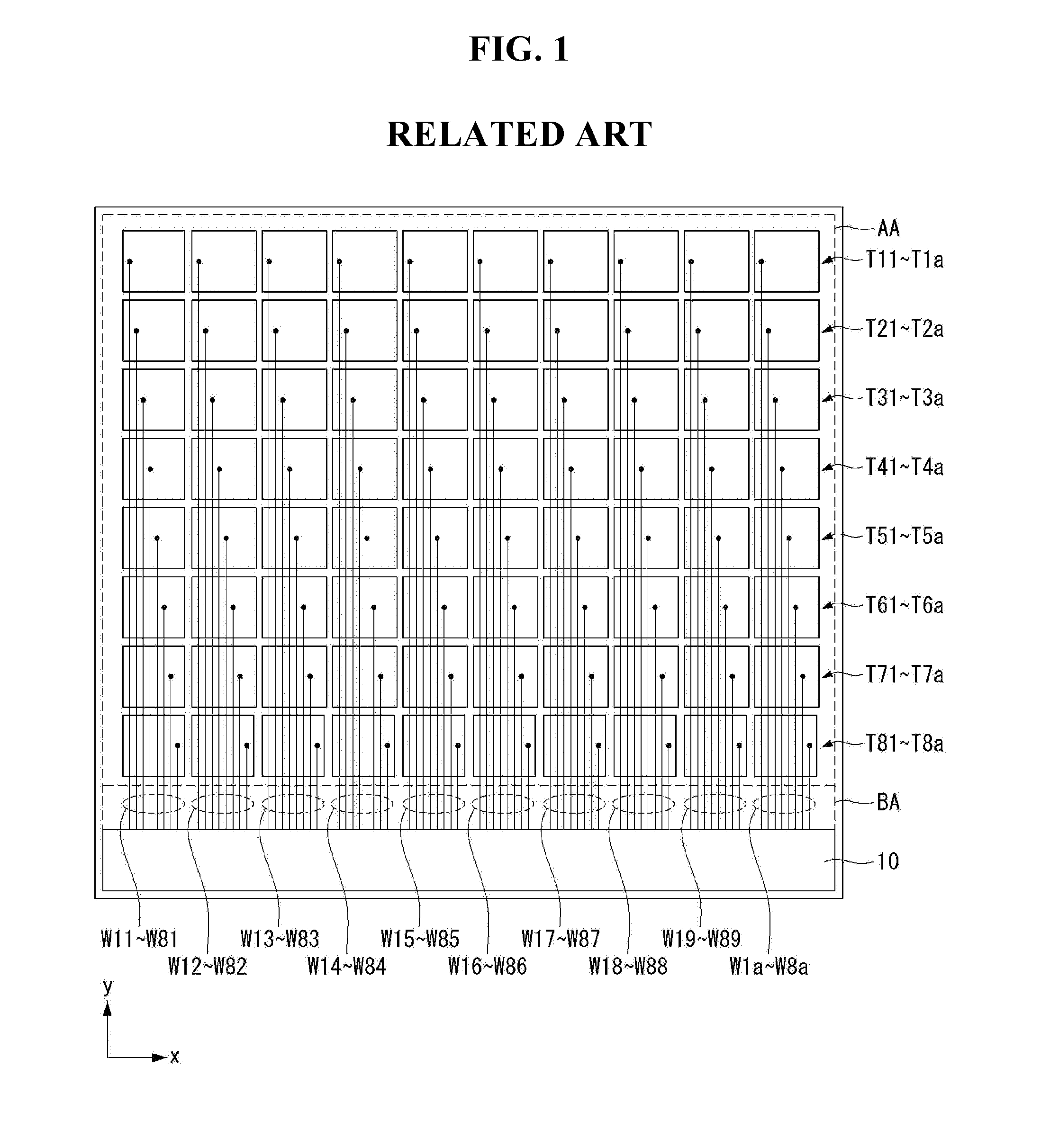
Further, when the touch / common routing wire is not connected to some of the touch / common electrodes so as to prevent the reduction of the aperture ratio, a touch location cannot be accurately recognized when the touch operation is performed on the touch / common electrode, to which the touch / common routing wire is not connected.
Thus, there is a limit to the size of the display device, to which the related art touch sensor integrated type display device can be applied.
Hence, the manufacturing cost of the display device increases.

Method used


Image

  • Touch Sensor Integrated Type Display Device
  • Touch Sensor Integrated Type Display Device
  • Touch Sensor Integrated Type Display Device

Examples


Embodiment Construction

[0062]Reference will now be made in detail to embodiments of the invention, examples of which are illustrated in the accompanying drawings. Wherever possible, the same reference numbers will be used throughout the drawings to refer to the same or like parts. It will be paid attention that detailed description of known arts will be omitted if it is determined that the arts can mislead the embodiments of the invention.

[0063]A touch sensor integrated type display device according to an exemplary embodiment of the invention may be implemented as in-cell type touch sensors embedded in a flat panel display, such as a liquid crystal display (LCD), a field emission display (FED), a plasma display panel (PDP), an organic light emitting diode display, and an electrophoresis display (EPD). In the following description, the embodiment of the invention will be described using the liquid crystal display as an example of the flat panel display. Other flat panel displays may be used.

[0064]The touch...


PUM


Abstract

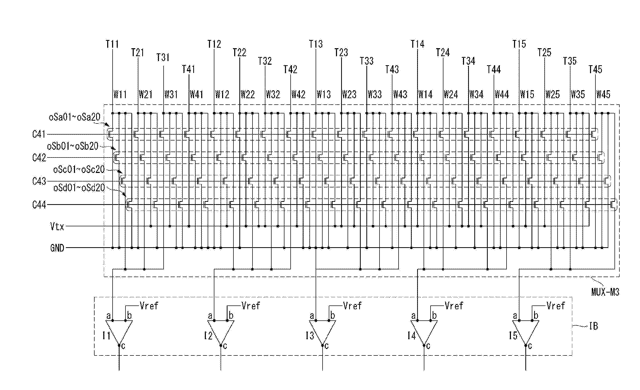
A touch sensor integrated type display device includes a display panel. The display panel includes a multiplexing unit that supplies a common voltage to touch / common electrodes of the display panel during a display driving period of one frame period of the display panel to display an image on the display panel. The multiplexing unit senses the touch / common electrodes using a self-capacitive method during a first touch driving period of the one frame period and a mutual capacitive method during a second touch driving period of the one frame period of the display panel to sense touch of the display panel.

Description

CROSS REFERENCE TO RELATED APPLICATIONS[0001]This application claims the benefit of Korean Patent Application No. 10-2015-0061264 filed on Apr. 30, 2015 and Korean Patent Application No. 10-2015-0174422 filed on Dec. 8, 2015, each of which is incorporated by reference in its entirety.BACKGROUND[0002]1. Field of Technology[0003]Embodiments of the invention relate to a touch sensor integrated type display device.[0004]2. Discussion of the Related Art[0005]In recent years, various input devices, such as a keyboard, a mouse, a track ball, a joystick, and a digitizer, have been used to allow users to interface with home appliances or information telecommunication devices. However, when the user makes use of these input devices, the user's dissatisfaction with the input devices increase because the user is required to learn how to use the input devices and the input devices occupy space. Thus, a demand for a convenient and simple input device capable of reducing erroneous operations is in...

Claims


Application Information

Patent Timeline
IPC IPC(8): G06F3/041G06F3/044G09G3/20G06F3/047
CPCG06F3/0412G06F3/0416G09G3/2096G06F3/044G06F3/047G06F2203/04104G06F2203/04106G06F3/041662G06F3/0446
Inventor KIM, CHEOLSEKIM, JUHANKIM, JINSEONG
Owner LG DISPLAY CO LTD
Learn More