System and method for liquefaction of natural gas

a natural gas and liquefaction technology, applied in the field of systems and methods for liquefaction of natural gas, can solve the problems of increasing the initial cost and running limited power produced by the expander, and insufficient to increase the outlet pressure, so as to achieve the effect of increasing the outlet pressure of the compressor and reducing the operating cost of the cooling uni

Inactive Publication Date: 2016-11-10
CHIYODA CORP
View PDF7 Cites 2 Cited by
  • Summary
  • Abstract
  • Description
  • Claims
  • Application Information

AI Technical Summary

Benefits of technology

[0061]As can be appreciated from the foregoing, the liquefaction system for the liquefaction of natural gas according to the present invention allows the outlet pressure of the compressor to be increased by using the power generated by the expander owing to the expansion of the material gas, and the cooling capacity that is required for the cooling unit to be reduced.

Problems solved by technology

However, in the conventional arrangement where the feedstock gas cooled by a cooling unit is expanded by an expander, the power produced from the expander is limited, and is inadequate for increasing the outlet pressure of the compressor to the desired level.
In the conventional arrangement, because the feedstock gas is required to be cooled before being expanded in the expander, a relatively large capacity is required for the cooling unit, and this increases the initial costs and the running costs of the cooling unit.

Method used


Image

  • System and method for liquefaction of natural gas
  • System and method for liquefaction of natural gas
  • System and method for liquefaction of natural gas

Examples


first embodiment

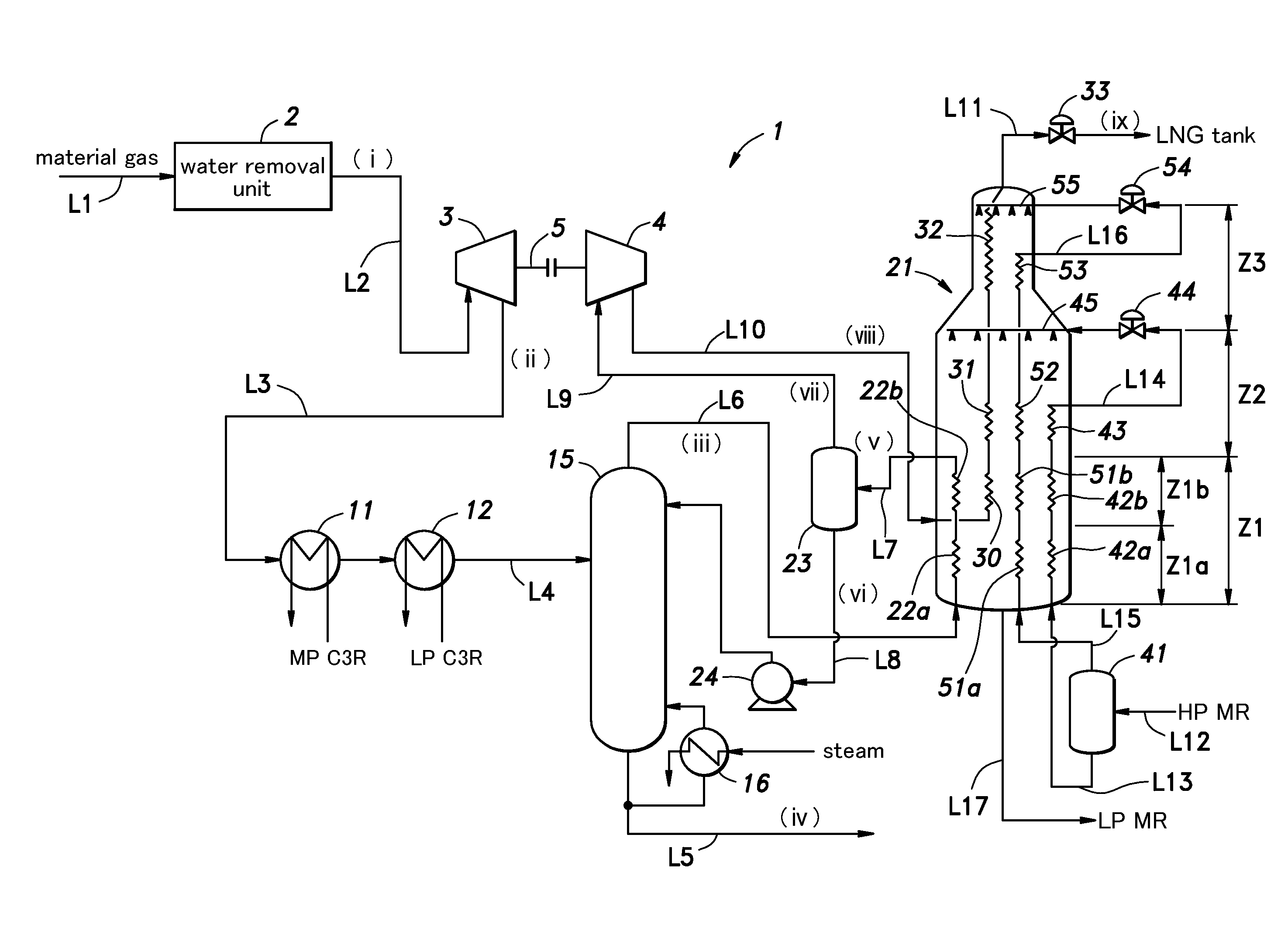
[0096]FIG. 1 is a diagram showing a liquefaction process flow in a system for the liquefaction of natural gas given as a first embodiment of the present invention. Table 1 which will be shown hereinafter lists the results of a simulation of the liquefaction process in the system for the liquefaction of natural gas. The same is similarly true with Tables 2 to 12. Table 1 shows the temperature, the pressure, the flow rate and the molar composition of the natural gas that is to be liquefied at each of various points in the liquefaction system of the first embodiment. In Table 1, columns (i) to (ix) show the values at the respective points in the liquefaction system 1 denoted with corresponding roman numerals (i) to (ix) in FIG. 1.

[0097]Natural gas containing about 80 to 98 mol % of methane is used as the material gas or the feedstock gas. The material gas also contains at least C5+ hydrocarbons by at least 0.1 mol % or BTX (benzene, toluene, xylene) by at least 1 ppm mol as heavier con...

second examples

(First and Second Examples for Comparison)

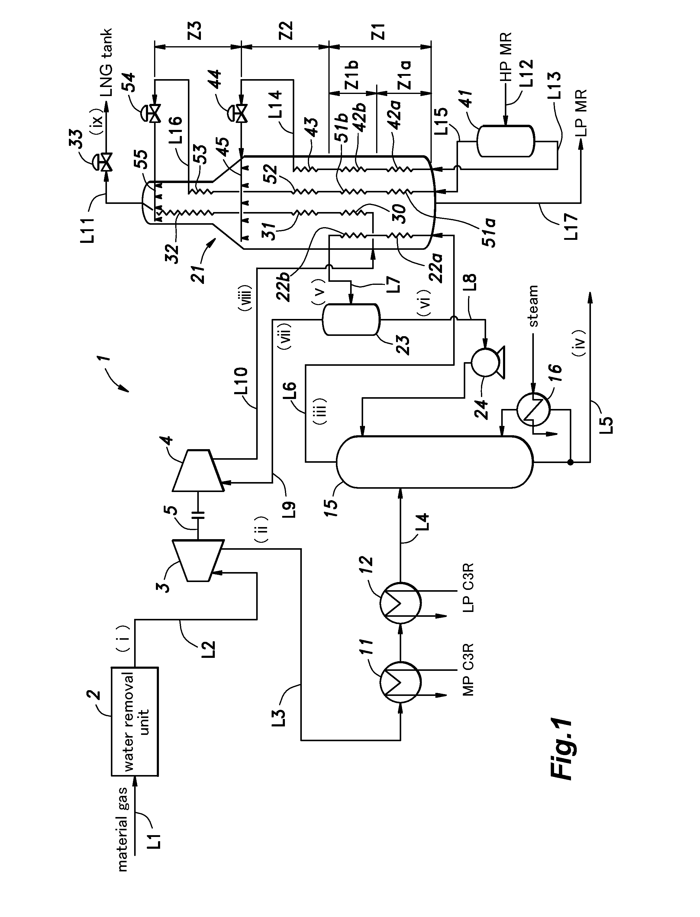
[0118]FIGS. 2 and 3 are diagrams showing liquefaction process flows in conventional systems for the liquefaction of natural gas given as a first and a second example for comparison with the first embodiment of the present invention. In the conventional liquefaction systems 101 and 201 for natural gas, the parts corresponding to those of the liquefaction system of the first embodiment are denoted with like numerals. Tables 2 and 3 show the temperature, pressure, flow rate and molar fractions of the material gas in the liquefaction systems of the first and second examples for comparison, respectively. It should be noted that the liquefaction system 201 of the second example for comparison is based on the prior art disclosed in Patent Document 1 (U.S. Pat. No. 4,065,278).

[0119]As shown in FIG. 2, the liquefaction system 101 of the first example for comparison is not provided with the first expander 3 and the first compressor 4 used in the lique...

second embodiment

[0148]FIG. 11 is a diagram showing a liquefaction process flow in a system for the liquefaction of natural gas given as a second embodiment of the present invention. Table 7 shows the temperature, the pressure, the flow rate and the molar composition of the natural gas that is to be liquefied at each of various points in the liquefaction system of the second embodiment by way of an example. In the liquefaction system illustrated in FIG. 11, the parts corresponding to those of the liquefaction system 1 of the first embodiment are denoted with like numerals and omitted from the following discussion except for the matters that will be discussed in the following.

[0149]The liquefaction system 1 of the second embodiment further includes a fourth compressor 71 for gas supply and a fourth cooler 72 on the upstream end of the line L1 for supplying the material gas to the water removal unit 2. In this liquefaction system 1, the material gas supplied from a line L18 is compressed by the fourth...


PUM


Abstract

By using the power generated by an expander by an expansion of material gas, the outlet pressure of a compressor is increased, and a requirement on the cooling capacity of a cooler is reduced. The liquefaction system (1) for natural gas comprises a first expander (3) for generating power by using natural gas under pressure as material gas; a first cooling unit (11, 12) for cooling the material gas depressurized by expansion in the first expander; a distillation unit (15) for reducing or eliminating a heavy component in the material gas by distilling the material gas cooled by the first cooling unit; a first compressor (4) for compressing the material gas from which the heavy component was reduced or eliminated by the distillation unit by using power generated in the first expander; and a liquefaction unit (21) for liquefying the material gas compressed by the first compressor by exchanging heat with a refrigerant.

Description

TECHNICAL FIELD[0001]The present invention relates to a system and a method for the liquefaction of natural gas for producing liquefied natural gas by cooling natural gas.BACKGROUND ART[0002]Natural gas obtained from gas fields is liquefied in a liquefaction plant so that the gas may be stored and transported in liquid form. Cooled to about −162 degrees Celsius, the liquid natural gas has a significantly reduced volume as compared to gaseous natural gas, and is not required to be stored under a high pressure. The natural gas liquefaction process at the same time removes impurities such as water, acid gases and mercury contained in the mined natural gas, and after heavier components having relatively high freezing points (C5+ hydrocarbons such as benzene, pentane and other heavier hydrocarbons are removed, the natural gas is liquefied.[0003]Various technologies have been developed for liquefying natural gas, including those based on expansion processes using expansion valves and turb...

Claims


Application Information

Patent Timeline
Patent Type & Authority Applications(United States)
IPC IPC(8): F25J1/00F25J3/02F25J1/02
CPCF25J1/0022F25J2230/60F25J1/0292F25J3/0209F25J1/0082F25J1/0085F25J1/0087F25J1/021F25J1/0216F25J3/0233F25J3/0238F25J2200/02F25J2240/04F25J2270/12F25J2270/18F25J2270/60F25J2220/68F25J2220/66F25J2200/76F25J2205/04F25J2220/64F25J2230/08F25J2230/20F25J2230/22F25J2240/02F25J1/0241F25J1/0204F25J5/00F25J2210/60F25J1/0035F25J1/0052F25J1/0055F25J1/0239F25J2200/72F25J2200/74F25J2230/30F25J2270/66F25J1/0262F25J3/0214F25J1/0218F25J2200/40F25J2205/02F25J2235/60F25J2240/40
Inventor KIKKAWA, YOSHITSUGISAKAI, KOICHIRO
Owner CHIYODA CORP
Why Eureka
Try Eureka